216
C
ha
ss
is
-
1
0
2012 Trip
Fluid Hot Check:
Fluid level rises as temperature increases.
Fluid must be at operating temperature to
ensure an accurate check. If a transmission
temperature gauge is not present, check the
fluid level when the coolant temperature gauge
has stabilized and the motorhome has been
driven for at least one hour.
Park the motorhome on a level surface
and shift to N (Neutral). Apply the
parking brake and allow the engine to
idle (500 to 800 RPM).
Check the fluid level. Safe operating
level is anywhere within the Hot Run
band on the dipstick.
The Hot Run band is approximately one
quart of fluid at operating temperature (above
170º F.). If the level is not within this band,
add or drain fluid as necessary to put the level
within the Hot Run band. Ensure fluid level
checks are consistent. Check the level more
than once. If readings are inconsistent, ensure
the transmission breather is not clogged.
Contact the nearest authorized Allison service
center if readings are inconsistent.
Fluid Change Interval:
The transmission fluid change intervals are
determined by:
When the Trans Service icon
illuminates.
Date/mileage as determined by Allison
in the OEM transmission owner’s
manual.
There are two filters in the transmission:
Main Filter and Lube Filter. Both filters are
replaced as a set.
Be sure to retain the receipt for proof of the
initial Main filter change. Refer to the Allison
transmission OEM manual or contact an
authorized Allison service center for service
intervals.
NOTE:
Date/mileage change intervals still
apply as specified in the Transmission
OEM Manual. Fluid must also be
changed whenever there is evidence
of impurities or high temperature
operation indicated by fluid
discoloration or strong odor. Refer
to the Allison transmission owner’s
manual or contact an authorized
Allison service center for fluid and
filter service intervals.
Health Monitor:
The health monitor checks the amount of
service life remaining of the internal clutches.
If the Trans Service icon remains illuminated,
the transmission must be inspected by an
authorized Allison service center for diagnosis
and repair.
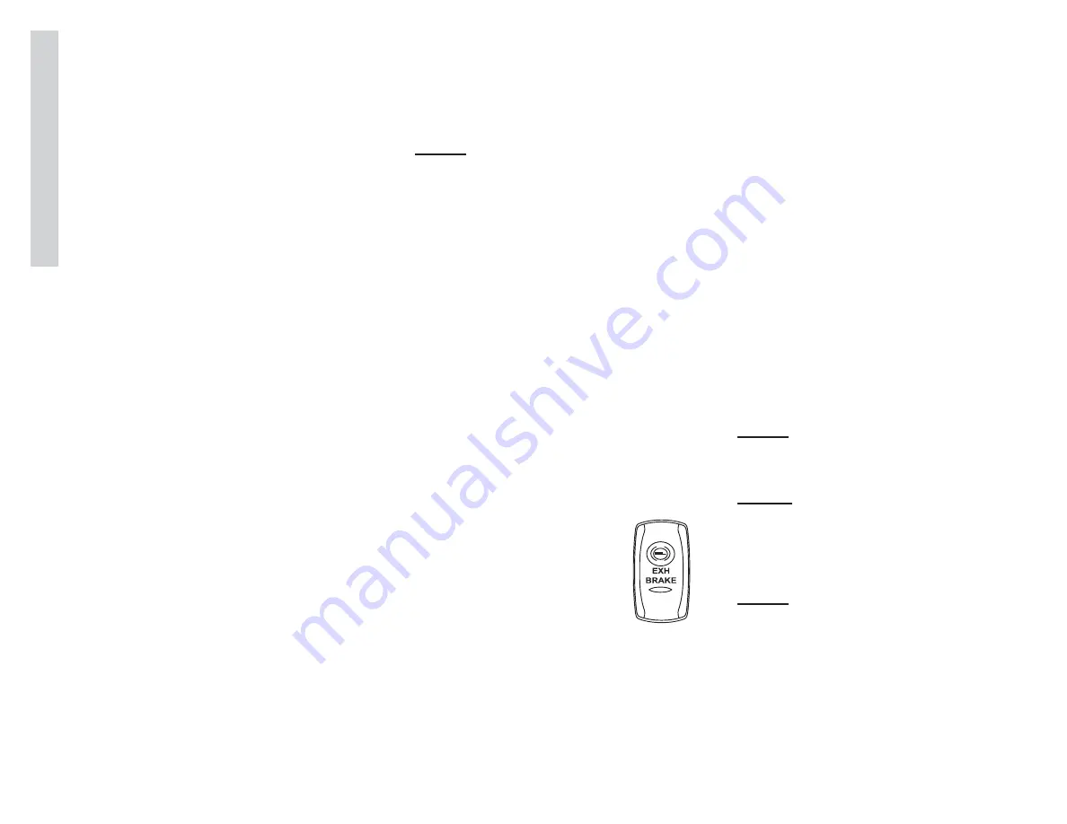
exHaUSt Brake
The exhaust brake is designed
to supplement the standard wheel
braking system. It is not designed to
bring the motorhome to a complete
stop. Use of the exhaust brake can
extend service life of brake linings.
The exhaust brake switch activates
the auxiliary brake.
To Engage the Exhaust Brake:
Turn on exhaust brake switch and
release the throttle to the idle position.
When activated, the exhaust brake will
restrict exhaust gases causing increased
back-pressure within the engine. Increased
back-pressure slows the speed of the engine
resulting in braking action. The amount of
engine braking force is relative to engine speed
(RPM).
When the auxiliary brake is activated going
down a hill, it can help control road speed
or sufficiently slow the road speed until the
transmission automatically downshifts to the
next lower gear. Downshifting automatically
occurs from high gear down to second gear.
Certain road conditions and engine speeds may
require the transmission be manually down-
shifted in order to generate adequate engine
RPM and increase the engine brake effect. If
the grade is steep, use the exhaust brake in
conjunction with the service brakes to control
road speed.
NOTE:
The brake lights will illuminate while
the exhaust brake is applied.
NOTE:
With the exhaust brake applied, road
speed can increase to the point the
transmission will automatically upshift
to prevent engine over-speed.
NOTE:
Activating the exhaust brake switch
does not cancel cruise control.
080498m
Summary of Contents for Trip 2012
Page 1: ...2 0 1 2 B YHOL I D A YR A MB L E R O w n e r s Ma n u a l...
Page 13: ...Notes...
Page 45: ...40 Driv ing Safety 2 2012 Trip Weight Record Sheet...
Page 51: ...46 Driv ing Safety 2 2012 Trip Notes...
Page 138: ...133 W ater Sy stems 6 2012 Trip Water System Diagram 040487va...
Page 139: ...134 Wat er Sy stems 6 2012 Trip Notes...
Page 151: ...146 Pro p ane Sy tems 7 2012 Trip Notes...
Page 173: ...168 Ho us e Electr ical 8 2012 Trip Notes...
Page 190: ...185 Chassis Electrical 9 2012 Trip Engine No Start Flow Chart...
Page 191: ...186 Ch as s is Electr ical 9 2012 Trip Notes...
Page 237: ...232 Ch assis 10 2012 Trip Notes...


