BA_PH_245-20_EN_15-22.docx
40
13.3.4
Height Adjustment via Target Value Input
Please note: Only one dimension (absolute or incremental) can be set at a time!
•
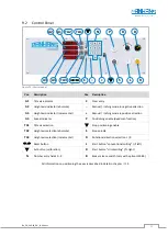
First activate the entry field for the height axis via the
“
TA2
” resp. “
TA3
”
button
→
LED next to
“
TA2
” resp. “
TA3
”
lights up.
•
Enter the new height via the number entry field
“
N
”
→
LED next to
“
TA2
” resp. “
TA3
”
flashes quickly (during value entry,
the display
“
TA2
” resp. “
TA3
”
indicates the angle entered).
•
Press the positioning button
“
P
”
and hold it down:
→
The entered value is accepted, enabled for positioning and positioned
→
The LED next to
“
TA2
” resp. “
TA3
”
flashes slowly until positioning is completed
→
The height position can be read at the same time in the display
“
A2
” resp. “
A3
”
→
The LED next to
“
TA2
” resp. “
TA3
”
lights up statically once the target position is reached
(actual value = target value)
→
The still active axis can be repositioned immediately via the number entry fields “
N
”
13.3.5
Calibrating the Height Axis Indicator
In order to permanently ensure exact positioning of the milling spindle height, the height axis indicator should
be checked for correctness at regular intervals and calibrated if necessary. To do this, proceed as follows:
Important:
First position the tilt axis exactly to 0.0° via tilt adjustment and display
“
A1
”
.
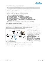
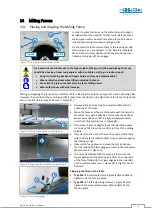
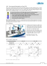
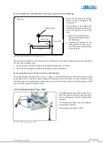
Figure 24: Calibrate height indicator
•
Remove the cutter and spacer rings as well
as any table insert rings.
•
Activate the entry field for the height axis
via the
“
TA2
”
button
→
LED
“
TA2
”
lights up.
•
In manual inching mode (section
press the
“
–
“ button
down until the support
surface for the spacer rings is below the
level of the table top edge.
•
Now place a straightedge over the table
opening on the table top.
•
Use buttons
“
P
”
and
“
+
”
to move gradually
upwards until the contact surface touches
the straightedge, see
point of contact (
B
).
•
For standard 30 mm spindle
→
Enter the value 80.0 via the number entry fields
“
N
”
.
For HSK-80 System (option)
→
Enter the value 85.0 via the number entry fields
“
N
”.
•
Then press the set button
for at least 3 seconds
→
The new value is adopted.
•
The indicator for the height axis is now calibrated.
Straightedge
Table top edge
Spindle
Support surface
for the spacer rings
B

