background image

25

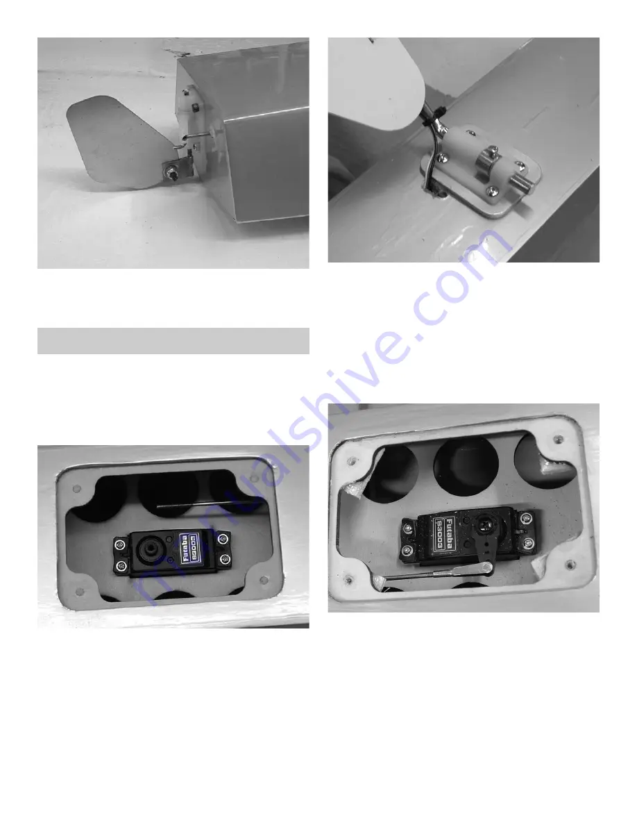
Servo Mounting

1.

†

Gather the following items

(2) servos
(2) 18” servo extensions
(2) 2-56 metal clevis

2.

†

Attach a 18” servo extension to each servo. 

†

Mount the two servos in the cutout provided

3.

†

Let the wire exit the float through a hole just to

the rear of the mounting plate.

†

Use small cable ties (not provided) to attach

the wire along the rear landing gear leg on the

back side.

.

†

Make a hole at the top of the gear leg to allow

the wire to enter the fuselage.

†

Seal the holes around the wire with sealant.

4.

†

Adjust the tension on the mounting screw to

allow the rudder to tilt up while sitting on land

or if it strikes something.

4.

†

Attach the clevis to the pushrod and your

servo arm.

Summary of Contents for Husky ARF

Page 1: ...in your area Per the Federal Communications Commission you are required to use only those radio frequencies specified for Model Aircraft LIMITED WARRANTY Lanier RC has inspected and certified the comp...

Page 2: ...cause the iron on covering to develop wrinkles This is not a fault of the manu facturer Please take a few minutes with your heating iron and heat gun to iron down the seams and re shrink the covering...

Page 3: ...get into the eye hold lid open and flush with water only Seek immediate medical atten tion CONSTRUCTION TIPS IMPORTANT ALWAYS READ A FEW STEPS AHEAD This will alert you to coming instructions and will...

Page 4: ...to full deflection in one direc tion about 1 and apply one drop of thin CA glue to each hinge Move the aileron to full deflection in the other direction and apply one drop of thin Ultra set CA on each...

Page 5: ...h the wing and exit the root rib IMPORTANT To ensure that any connections locat ed inside the wing will not come loose either when the wires are pulled or during flying always tape them securely toget...

Page 6: ...of the door Mark the loca tion of the mounting blocks 12 Epoxy the servo mounting blocks in place and mount the servo 13 Attach a servo arm to the servo and hook the pushrod to the arm You will need...

Page 7: ...e at each location 3 Mount the straps using the 4 x 1 2 flat head screws 4 Install the wheels with a wheel collar on each side 5 Install the gear fairing using the cable ties Start from the back side...

Page 8: ...of the top collar Adjust the tiller arm so it is square with the axle Tighten both set set screws and both bolts 4 Cut the head off the 4 40 screws and install the nylon pushrod ends 5 Install the whe...

Page 9: ...ab will be square to the fuselage Sight down the fuselage to the wing and make sure the stab is parallel to the wing Shim one side if necessary 5 When satisfied with the alignment mark the stab top an...

Page 10: ...tall a rigging coupler on each side of the stab top and bottom 6 Install the other two couplers on the bottom of the fuselage just in front of the tail wheel bracket using the two 4 screws 7 Insert th...

Page 11: ...ances on the tip do not interfere with the stab 3 When satisfied with the fit hold the elevator tight against the stab and move to its full deflection in one direction Glue hinges in place with thin...

Page 12: ...l lengths Attach one end of the braided cable to each side of the arm using the swages It is best on control surfaces to loop the cable back through the swage before crimping to make sure it does not...

Page 13: ...ion on the elevators and drill a 9 64 hole at each spot 3 Use thin Ultra Set CA to harden the holes Assemble the control horn No washer on top cup washer on bottom followed by the ball nut Screw the p...

Page 14: ...ution Always use thead lock on any bolt that is threading into metal threads 2 The firewall has a cross hairs marked which is the center of where your crank shaft should be Drill the holes from which...

Page 15: ...wn There is a mount on both sides of the fuselage in case your throttle is on the opposite side 7 Locate the e z throttle connector and assem ble to your servo as shown Insert the pushrod into the con...

Page 16: ...top of the tank and the clunk where it is 1 4 off the bottom of the tank when held ver tical It is a good idea to use cable ties on the fuel lines to prevent them from coming off cable ties not inclu...

Page 17: ...is is the position of the four cowl mounting screws Mark a mark on the paper that will be in the center of the overhang Take another piece of paper about 7 x 2 and make a cutout that will fit around t...

Page 18: ...a Set thin CA and harden the 1 16 holes for the cowl mount Reposition the cowl and mount using the four 4 screws Wing Struts 1 Collect the following items 1 Fuselage strut attach bracket s 4 4 40 x 1...

Page 19: ...ackets in the cutout in the bottom of both wings 5 Locate the two wing struts 6 Screw a 4 40 clevis with silicone keeper on all four of the ends 7 slide the aluminum tube into the fuselage and attach...

Page 20: ...nds of the interplane struts 9 Attach the struts to the plane 10 Bend the nylon tab on the end of the inter plane strut 90 degrees to the strut and attach to the strut and to the wing using the 2 x 3...

Page 21: ...asking tape to hold in place till the glue dries 3 Fit the side windows in from the inside Some trimming of the flanges may be necessary to allow the glass to fit all the way into the hole and flush w...

Page 22: ...place 2 The area just under the front window is wood to provide a place to mount the switch It can be mounted on either side to keep it away from the exhaust 3 The batteries can be placed between the...

Page 23: ...ts on the floats with the 4 40 screws Use lock tite on the screws Remove the wheels from the main landing gear 3 Mount the main landing gear leg in the front brackets using one of the 1 4 wheel collar...

Page 24: ...ackets on the rear of the floats using the 4 40 x 1 2 screws Use lock tite on the screws 3 Assemble the rudder as shown Bolt the rud der to the mount using the 4 40 bolt and air craft nut The bracket...

Page 25: ...to the rear of the mounting plate Use small cable ties not provided to attach the wire along the rear landing gear leg on the back side Make a hole at the top of the gear leg to allow the wire to ente...

Page 26: ...e flush with the rear of the fuselage and centered on the cen terline you drew 4 Drill 1 16 holes at the 6 locations and mount plate using the 4 screws 5 Replace the flying wires 5 Epoxy the sub fin t...

Page 27: ...4 Stroke 25080 Also available Also available as a kit as a kit Street Price 124 99 Dart 40 ARF Wingspan 63 Wing Area 630 sq in 40 46 2 Stroke or 4 Stroke 4 Channel Radio 26090 Street Price 199 99 P O...

Page 28: ...lso available as kits The Stinger Series is also available as kits All wood built up ARFs All wood built up ARFs with fiberglass cowl with fiberglass cowl wheel pants wheel pants All wood built up ARF...

Page 29: ...E E EA AR RL LY Y A AR RL LY Y A AR RF F A AR RF FS S S S Street Price 189 99 Street Price 279 99 Street Price 604 99 Street Price 119 99 Street Price 79 99 Street Price 74 99 Street Price 114 99 Str...

Page 30: ...30 0 Wingspan 35 Req Brushless Motor 25077 G G G GI IA AN NT T I IA AN NT T S S S SC CA AL LE E C CA AL LE E K K K KI IT TS S I IT TS S Street Price 34 99 Won t break Won t break like foam like foam 1...

Page 31: ...ent model airplane kits from Lanier RC Precision lasercut parts and comput er generated plans assure performance right from the start All kits include detailed instructions and fea ture fast assembly...

Page 32: ...HT ENGINE RADIO 67 64 864 Sq In 8 to 9 lbs 60 to 90 2 Stroke 90 to 1 20 4 Stroke 4 Channel 6 Servos Carl Goldberg Products PITTS MONSTER EP ARF E EL LE EC CT TR RI IC C P PO OW WE ER R Wingspan Overal...

Page 33: ...ical airfoil rewards experienced flyers with graceful aerobatics Carl Goldberg s Falcon 56 Mark II ARF is built with the quality craftsmanship you expect from an experienced builder This 90 pre built...

Page 34: ...s back and available as an ARF Features flaps wing struts and complete hardware package Classic WING SPAN WING AREA LENGTH WEIGHT POWER RADIO 56 558 Sq In 47 3 4 5 6 LBS 40 46 2 Stroke 4 Chan 5 Servo...

Page 35: ...otor 4 Channel 4 Micro 4 Channel 4 Micro Servos Servos Super CHIPMUNK 400 ARF ARF 12023 W Wing S ing Sp pan 37 3 4 an 37 3 4 W Wing ing Area 217 Sq In Area 217 Sq In Requires Brushless Requires Brushl...

Page 36: ...atic champ is capable of any full stall thrust vec tored maneuvers you can command Double beveled oversized control surfaces deliver unbeatable aerobatic performance You can engage the oversized flaps...

Page 37: ...hen you re ready to return to earth you can count on its slow as a walk feather soft landings Decathlon ARF It s easy to see why the Decathlon is a leader among aerobatic champions clean lines long ta...

Page 38: ...stability smooth ground handling and take offs enhanced climb to glide transitions and slow as a walk landings The only difference between the Eagle 2 and this ARF version is that this one gets you to...

Page 39: ...modification Ready to install with pre covered built up pontoon floats Includes all mounting hardware for the Anniversary Edition Piper Cub ARF Superfloats ARF 12296 Supterfloats Kit 296 A Al ls so o...

Page 40: ...ies are available in 3 sizes small size for 6 12 lb medium for 10 18 lb and large for 16 35 lb airplanes Main Landing Gears Profile Landing Gears Goldberg Landing Gears are lightweight and extremely d...

Page 41: ...VISIT US AT WWW CARLGOLDBERGPRODUCTS COM P O Box 818 Oakwood GA 30566 Phone 678 450 0085 Fax 770 532 2163...

Page 42: ...VISIT US AT WWW CARLGOLDBERGPRODUCTS COM P O Box 818 Oakwood GA 30566 Phone 678 450 0085 Fax 770 532 2163...

Page 43: ...VISIT US AT WWW CARLGOLDBERGPRODUCTS COM P O Box 818 Oakwood GA 30566 Phone 678 450 0085 Fax 770 532 2163...

Page 44: ...VISIT US AT WWW CARLGOLDBERGPRODUCTS COM P O Box 818 Oakwood GA 30566 Phone 678 450 0085 Fax 770 532 2163 Goldberg Spinners...

Reviews: