


EQUIPMENT INST
ALLA
TION
18
5.5 Remote Display Installation
The Remote Display should be installed on a wall, inside the building, where it can be seen by
crew personnel. Installation of the Remote Display requires one hole to be drilled through the
wall for cable routing, and two screw holes for mounting the unit on the wall of the building.
Follow the instructions below.
●
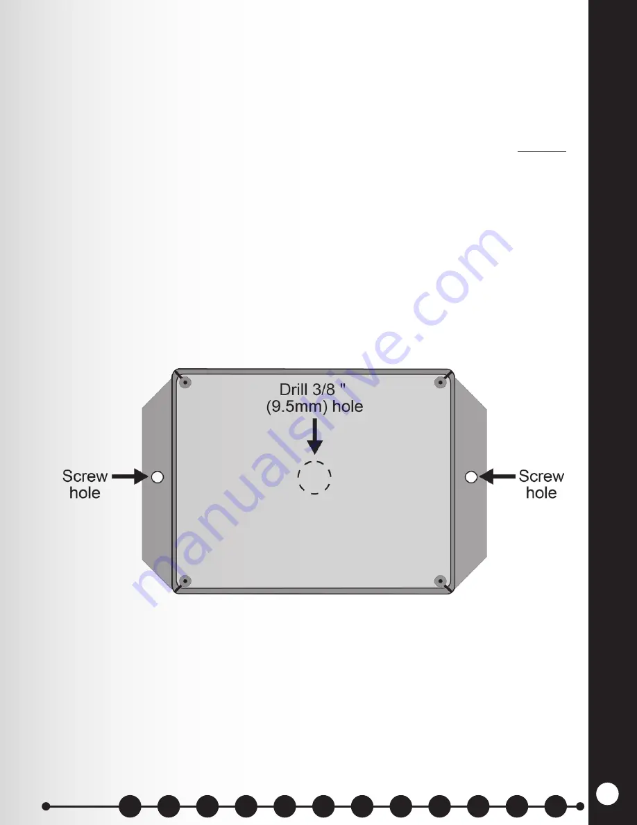
Drill a 3/8 inch (9.5mm) hole in the wall where the display unit will be mounted.
●
Remove the front panel and attached circuit board from the display unit enclosure, and drill
a 3/8 inch (9.5mm) hole centered through the back of the enclosure as shown in Figure 11.
NOTE:
This is for mounting the unit directly over a cable hole in the wall. If you do not want
to mount the unit over the cable hole, you can drill a hole in one of the sides of the display
enclosure.
●
Hold the display enclosure against the wall so the hole in the center of the enclosure is over
the hole in the wall, and mark the wall through the two screw holes in the flanges on the
sides of the enclosure.
●
Set the display enclosure aside and drill two 3/16 inch (4.8 mm) screw holes at the marked
spots, deep enough to insert the enclosed screw anchors.
●
Insert the enclosed screw anchors completely into the two screw holes in the wall.
● Hold the display enclosure against the wall so the screw holes in its flanges are over the
screw anchors on the wall, and screw the two enclosed screws through the holes and all the
way into the screw anchors.
●
Using the enclosed 5 pin connectors, connect cable according to the wiring diagrams.
Figure 10. Mounting the Remote Display Unit
Sections
Summary of Contents for 6700HD
Page 1: ...SYS6700HD Drive Up Communication System Installation Instructions HME 400G754 Rev D 4 26 17...
Page 2: ......
Page 7: ......
Page 62: ...SYSTEM 6700HD BLOCK DIAGRAM Figure 18 System 6700HD Block Diagram 55...
Page 63: ...Figure 19 RS485 Digital Communications Link RS485 DIGITAL COMMUNICATION LINK 56 56...
Page 68: ...Figure 24 Power Supplies WIRING DIAGRAM FOR POWER SUPPLIES 61 61...


