background image


25 


C07UE001-1804 


4


Install End Effector 

4-1


Installation Notice 

When you install the end effector, please obey the following items. 


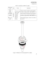
Figure 4-1 Recommended Installation Illustration for Ball End Effector 


1.


Don’t remove or change any mechanical stopper on the robot by yourself. 

2.


When  you  install  the  end  effector  on  ball  screw  spline,  please  install  it  at 
30mm  on  the  lower  end  of  ball  screw  spline  and  fix  with  the  threaded 
structure over M4. 

3.


When  you  install  the  end  effector,  please  note  weight,  static  torque  and 
rotation inertia are in the motion range. For the method to calculate static 

torque  and  rotation  inertia,  please  refer  to  4-2  Overview  for  Calculating 
Static Torque and Rotation Inertia. 


If  there  are  some  doubts  on  weight,  static  torque  and 
rotation inertia, please contact us or the agent. 

(30 mm End 

effector clamp) 

(Threaded structure) 

Summary of Contents for RS403

Page 1: ...www hiwin tw User Manual SCARA Robot RS403...

Page 2: ...ideway Automation Semiconductor Medical Ball Type HG EG WE MG CG Quiet Type QH QE QW QR Other RG E2 PG SE RC Medical Equipment Hospital Rehabilitation centers Nursing homes Robotic Gait Training Syste...

Page 3: ...886 4 23594510 Fax 886 4 23594420 E mail business hiwin tw Website http www hiwin tw Copyright The contents in this manual are used for the authorized customers and suppliers This manual should not b...

Page 4: ...III C07UE001 1804 Revision History Version Date Remark Ver1 0 2017 08 First issuance Ver1 1 2017 11 Added the Ball Screw Spline lubrication Ver1 2 2018 04 Added End extending load...

Page 5: ...Safety Symbol 12 1 3 Operation Notice 14 1 3 1 Run Alert Area 14 1 3 2 Temperature Error 14 1 3 3 Flammability Alert 14 1 3 4 Humidity Error 15 1 3 5 High Voltage 15 1 4 Emergency Stop 15 1 4 1 Robot...

Page 6: ...a 29 Maintenance 31 5 Robot Maintenance 32 5 1 Cover 32 5 1 1 Disassemble Cover 33 5 1 2 Install Cover 34 5 2 J3 J4 Axes 35 5 2 1 Check J3 J4 Belts 36 5 3 Grease Lubrication 39 5 3 1 Lubrication of Ba...

Page 7: ...ted responsibilities After you read this manual please keep it well so that can be read any time About Manual This manual describes the SCARA Robot developed by HIWIN whose structure includes the body...

Page 8: ...ation The failure after the warranty period is expired will be charged Failure and damage caused by incorrect operation different from the manual Reconstruct or remove the robot by yourself Failure an...

Page 9: ...n t be stopped and avoided in time the death or serious injury could take place WARNING symbol represents a potential danger condition If it can t be solved in time the injury or death could take plac...

Page 10: ...stment on the SCARA Robot please contact customer service Please prepare the following information when you contact us Customer Service Customer hotline 866 4 23594510 E mail business hiwin tw System...

Page 11: ...10 C07UE001 1804 About Safety...

Page 12: ...operators Please carefully read the description in this manual so that can efficiently and safely operate the robot The operators must be familiar with the position the function and operation for saf...

Page 13: ...area to avoid damage or injury when the robot is operated C There is a high voltage label on the SCARA Robot Permissible voltage and the maximum current for the robot are 1P 200 240VAC and 10A A user...

Page 14: ...13 C07UE001 1804 RS403 400 150 N Figure 1 1 Illustration for Safety Symbol Don t remove the safety symbol If it is lost please contact us or the agent...

Page 15: ...the robot is operated the operator should pay attention to the motion range for damage 1 3 2 Temperature Error When the robot is operated the heat source comes from the electronic parts in the contro...

Page 16: ...3 5 High Voltage 1P 200 240VAC is supplied to the robot Once electric leakage or touch by accident takes place it will cause serious injury or death When you install the robot you need to check each c...

Page 17: ...Axes J1 axis Move Arm A after you press the BRAKE RELEASE button J2 axis Move Arm B after you press the BRAKE RELEASE button J3 axis Rotate ball screw spline after you press the BRAKE RELEASE button...

Page 18: ...electronic parts The maximum permissible inertia can reach 0 05 kg m2 2 2 Model Name RS403 400 150 N The robot is operated in the standard environment The accessories with additional coating are inst...

Page 19: ...mes on Robot Figure 2 2 Illustration from the Direction A of Figure 2 1 Arm A Arm B BRAKE RELEASE button Status Indicator 4 pneumatic connector 6 pneumatic connector Ball screw spline View from Direct...

Page 20: ...19 C07UE001 1804 RS403 400 150 N Figure 2 3 Part Dimensions for Robot This dimension diagram is used for the reference based on the approved ones or the actual ones...

Page 21: ...gure 2 4 Motion Range for Robot All motion ranges in this diagram is used for the reference The dimensions are based on the approved diagrams or the delivered machines The working range in this diagra...

Page 22: ...mum arm length Arm A and Arm B mm 400 Maximum motion range J1 deg 128 J2 deg 130 J3 deg 360 J4 mm 150 Cycle time sec 0 42 Repeatability J1 J2 mm 0 01 J3 deg 0 01 J4 mm 0 01 Maximum axial speed J1 deg...

Page 23: ...Keep away from impact or vibration Keep away from a source of electromagnetic interference The robot is not suitable in the coating environment If it is operated at the place where doesn t meet the c...

Page 24: ...ou install the robot the working range must be taken into account If the end effector is installed the maximum motion range will vary depending on the position and overhang of the end effector Therefo...

Page 25: ...uthorized staff can operate crane or forklift only When those without authorization perform the operations above mentioned the surrounding operators could be injured or the robot could be damaged Tran...

Page 26: ...rew spline please install it at 30mm on the lower end of ball screw spline and fix with the threaded structure over M4 3 When you install the end effector please note weight static torque and rotation...

Page 27: ...0N m Please obey the operating condition If the torque exceeds this value the performance and lifetime will be reduced Formula to calculate static torque M torque F force L overhang plus total arm len...

Page 28: ...into account Please calculate if total rotation inertia at the end of ball screw spline is within rated maximum permissible inertia If rotation inertia is greater than the value the performance and l...

Page 29: ...the basic shape and determine rotation inertia of the object a Rotation inertia of rectangle b Rotation inertia of cylinder c Rotation inertia of sphere Mass Center of gravity position of rectangle O...

Page 30: ...will vary depending on the shape of the load It is recommended that the actual calculation of the inertia be done Figure 4 3 RS403 400 150 N arm end extension load diagram Figure 4 4 Load center of g...

Page 31: ...30 C07UE001 1804 Figure 4 5 Load center of gravity and motor speed for 3KG load spline length 330mm...

Page 32: ...31 C07UE001 1804 Maintenance...

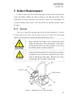
Page 33: ...three drive belts You can remove the cover to check there are foreign objects in Arm B ball screw spline is damage and the belts are worn Please disconnect the power on the control panel and unplug t...

Page 34: ...f Dissembling Cover for Robot Don t force to disassemble the cover Otherwise it could cause poor cable contact or damage as well as electric shock or robot failure Don t remove the cable sleeve when y...

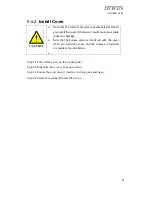
Page 35: ...or damage Note that ball screw spline is interfered with the cover when you install the cover and the screws are fastened to complete the installation Step 01 Turn off the power on the control panel...

Page 36: ...re controlled A user can remove the cover to check there is any failure inside the Arm B Please press the Emergency Stop button before the maintenance Don t make any maintenance when the robot runs so...

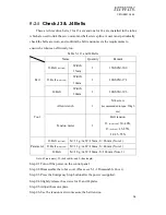
Page 37: ...mm 1 100 S3M 396 Tool Allen wrench 1 M4 screw recommended torque 55kgf cm Tension meter 1 Belt tension J3 motor end 30 40N J3 ball end 45 55N J4 45 55N Parameter J3 Belt ball end M 1 3 g m W 15mm S 86...

Page 38: ...requirement Step 08 Check the motors of J3 and J4 axes as well as screws for middle wheel Step 09 Turn off the power on the control panel Step 10 Install the robot cover RS403 400 150 N Belt Tension...

Page 39: ...ust be kept clean It is recommended ball screw spline be cleaned and maintained every three months to keep smoothly running Please press the Emergency Stop button and disconnect the power prior to the...

Page 40: ...all Screw Spline Figure 5 4 Illustration for Lubricating Ball Screw Spline 4 M3 flat washer 4 M4 flat washer Lubricate the surface of ball screw spline and the grooves with HIWIN G04 Roller screw nut...

Page 41: ...line bearing Lubrication Check once per three month when the running distance reaches 200km Fill new lubricant into the nut opening 1 5 and remove old grease Recommended fill 2c c Flat spline bearing...

Page 42: ...ld be replaced by the trained or authorized engineers only to avoid the accuracy and lifetime of the robot Table 5 4 Decelerator Lubrication Area to apply grease Operation Reference Diagram Flexible b...

Page 43: ...he Arm A Step 03 Remove the M6 screws and washer for Arm A Step 04 Remove the M5 screws and washer for the decelerator and the motor plate Step 05 Disassemble the decelerator upwardly in the vertical...

Page 44: ...erator and the Arm B Step 06 Disassemble the decelerator upwardly in the vertical direction Figure 5 7 Illustrations of Dissembling Decelerator for Robot J2 Please keep each origin part and component...

Page 45: ...fter power failure takes place A user must periodically replace them to ensure the robot coordinates can be memorized Please press the emergency button and disconnect the power prior to the maintenanc...

Page 46: ...ies in order Step 04 Install new batteries in order primary lithium battery 3 6V 2 4AH for TADIRAN No 3 Step 05 Turn off the power on the control panel Step 06 Install Wiring Panel please see Step 07...

Page 47: ...trol panel Check the appearance is dirty or damaged and clean and wipe it Robot appearance Appearance of communication cable Appearance of control panel Check the communication cables power cables pne...

Page 48: ...takes place owing to the fan failure the robot will stop the operation Please contact customer to replace the fan The motor drivers at each axis are equipped with a protection mechanism The high tempe...

Page 49: ...e robot depends on the fixtures or objects loaded on ball screw spline If the loads exceed the requirements a user can maintain the normal operation of the robot by changing the system setting or seek...

Page 50: ...49 C07UE001 1804 Opinion Response Issue Actual condition Use Advice E mail business hiwin tw Customer hotline 866 4 23594510...

Page 51: ...improvements 3 HIWIN will not sell or export those techniques and products restricted under the Foreign Trade Act and relevant regulations Any export of restricted products should be approved by comp...

Page 52: ...IWIN CHINA SUZHOU CHINA www hiwin cn info hiwin cn Mega Fabs Motion System Ltd HAIFA ISRAEL www mega fabs com info mega fabs com HIWIN GmbH OFFENBURG GERMANY www hiwin de www hiwin eu info hiwin de HI...

Reviews: