background image

OPERATING THE MACHINE

5-2

M1J1-01-022

1

3

2

4

5

8

6

7

M104-05-001

M104-05-002

4

3

1

2

6

5

8

7

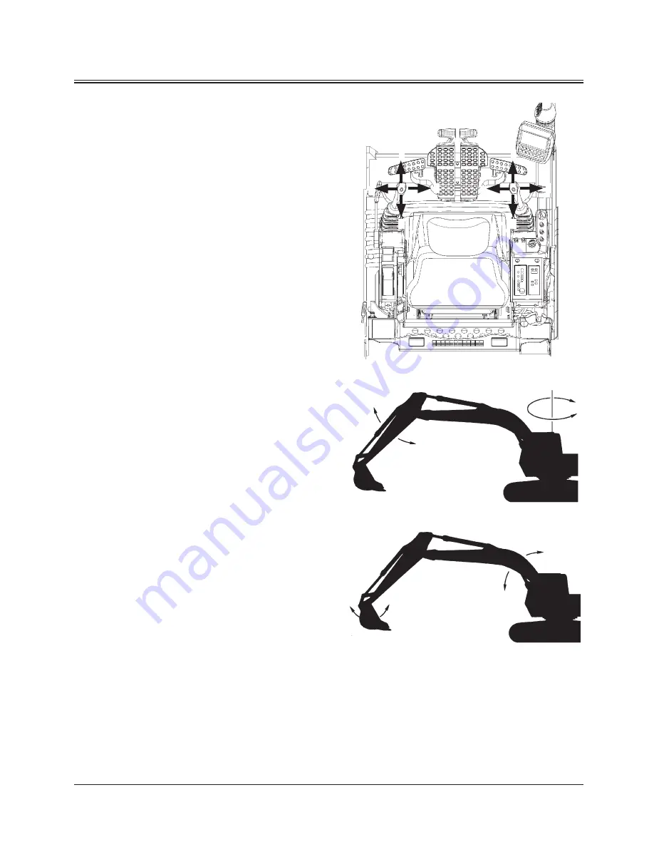
CONTROL LEVER (HITACHI PATTERN)

d

  WARNING:  Never place any part of body beyond 

window frame. It could be crushed by the boom 

if boom control lever is accidentally bumped or 

otherwise engaged. If window is missing or broken, 

replace immediately. 


Prevent possible injury from unexpected machine 

movement.


Make sure you know the location and function of 

each control before operating.

The machine is equipped with a label showing the control 

patterns of the levers and pedals.

IMPORTANT:  When digging, avoid hitting tracks with 

boom cylinders. 


When digging over the end of the tracks, 

travel motors should be at the rear to 

maximize machine stability and lift 

capacity.

When a lever is released, it will automatically return to neutral, 

and that machine function will stop.

1-  Swing Right
2-  Swing Left
3-  Arm Roll-In
4-  Arm Roll-Out
5-  Boom Lower
6-  Boom Raise
7-  Bucket Roll-In
8-  Bucket Roll-Out

Summary of Contents for ZAXIS 450LC-3

Page 1: ...Serial No 020001 and up Hydraulic Excavator PART NO EM1J3 NA1 2 450LC 3 650LC 3 850LC 3 ...

Page 2: ... ...

Page 3: ...ETTING ON OFF THE MACHINE OPERATOR S STATION BREAK IN OPERATING THE ENGINE DRIVING THE MACHINE OPERATING THE MACHINE ASSEMBLING MAINTENANCE MAINTENANCEUNDERSPECIALENVIRONMENTALCONDITIONS STORAGE TROUBLESHOOTING SPECIFICATIONS OPTIONALATTACHMENTSANDDEVICES INDEX ...

Page 4: ......

Page 5: ...ial Nos in the blank spaces in this group to immediately make them available upon request MACHINE MODEL TYPE PRODUCT IDENTIFICATION NUMBER PRODUCT IDENTIFICATION NUMBER PRODUCT IDENTIFICATION NUMBER fNOTE ENGINE TYPE AND SERIAL NUMBER TYPE MFG NO TRAVEL MOTOR TYPE AND SERIAL NUMBER TYPE MFG NO M157 00 001 M111 07 010 M1J1 00 001 HCM1J300P00020001 PRODUCT IDENTIFICATION NUMBER PIN Marks to indicate...

Page 6: ...MACHINE NUMBERS M17P 01 001 SWING MOTOR TYPE AND SERIAL NUMBER TYPE MFG NO M17V 00 002 ZX650LC 3 ZX850LC 3 M16J 07 007 M1J7 07 005 ZX650LC 3 ZX450LC 3 ...

Page 7: ...MACHINE NUMBERS M1JB 00 001 HYDRAULIC PUMP TYPE AND SERIAL NUMBER TYPE MFG NO ZX850LC 3 M1J1 001 ZX450LC 3 M1J7 07 003 ZX650LC 3 850LC 3 ...

Page 8: ...MACHINE NUMBERS BOOM TYPE AND SERIAL NUMBER TYPE MFG NO ARM TYPE AND SERIAL NUMBER TYPE MFG NO BUCKET TYPE AND SERIAL NUMBER TYPE MFG NO M111 12 005 M17V 00 005 M116 12 004 ...

Page 9: ...nt Parts from Flying S 23 Store Attachments Safely S 23 Prevent Burns S 24 Replace Rubber Hoses Periodically S 24 Avoid High pressure Fluids S 25 Prevent Fires S 26 Evacuating in Case of Fire S 27 Beware of Exhaust Fumes S 27 Precautions for Welding and Grinding S 27 Avoid Heating Near Pressurized Fluid Lines S 28 Avoid Applying Heat to Lines Containing Flammable Fluids S 28 Remove Paint Before We...

Page 10: ...ies 3 9 Stopping the Engine 3 11 DRIVING THE MACHINE Drive the Machine Carefully 4 1 Steering the Machine Using Pedals 4 2 Steering the Machine Using Levers 4 3 Travel Mode Switch 4 4 Travel Alarm Optional 4 4 Operating on Soft Ground 4 5 Raise One Track Using Boom and Arm 4 5 Towing Machine a Short Distance 4 6 Operating in Water or Mud 4 7 Parking the Machine on Slopes 4 8 Parking the Machine 4 ...

Page 11: ...ent of Parts 7 10 Maintenance Guide 7 11 A Greasing 7 17 Automatic Lubrication If Equipped 7 17 Automatic manual Lubrication If Equipped 7 19 Electric Grease Gun 7 23 Electric Grease Gun If Equipped 7 31 Lubricator If Equipped 7 33 Front Joint Pins Backhoe 7 37 Swing Bearing 7 39 Swing Internal Gear 7 40 B Engine 7 41 Engine Oil Level 7 41 Change Engine Oil 7 42 Replace Engine Oil Filter 7 42 C Tr...

Page 12: ...chine from Storage 10 2 TROUBLESHOOTING Impossible to Start the Engine 11 1 Engine 11 2 Electrical System 11 6 Mode Selection 11 8 Control Levers 11 9 Hydraulic System 11 9 SPECIFICATIONS Specifications Backhoe 12 1 Working Ranges Backhoe 12 2 Shoe Types and Applications 12 3 Bucket Types and Applications Backhoe 12 4 Specifications 12 5 Working Ranges 12 6 Shoe Types and Applications 12 7 Bucket ...

Page 13: ...ury WARNING indicates a potentially hazardous situation which if not avoided could result in death or serious injury CAUTION indicates a potentially hazardous situation which if not avoided may result in minor or moderate injury DANGER or WARNING safety signs are located near specific hazards General precautions are listed on CAUTION safety signs Some safety signs don t use any of the designated s...

Page 14: ...ized by Hitachi Failure to do so may deteriorate the safety function and or service life of the machine In addition personal accident machine trouble and or damage to material caused by using unauthorized attachments and or optional parts or equipment will void Hitachi Warranty Policy The safety messages in this SAFETY chapter are intended to illustrate basic safety procedures of machines However ...

Page 15: ... machine Operating equipment safely requires the full attention of the operator Do not wear radio or music headphones while operating the machine 005 E01A 0438 PROTECT AGAINST NOISE Prolonged exposure to loud noise can cause impairment or loss of hearing Wear a suitable hearing protective device such as earmuffs or earplugs to protect against objectionable or uncomfortably loud noises 006 E01A 043...

Page 16: ...e Refrain from listening to the radio or using music headphones or mobile telephones in the cab while operating the machine Keep all flammable objects and or explosives away from the machine After using the ashtray always cover it to extinguish the match and or tobacco Do not leave cigarette lighters in the cab When the temperature in the cab increases the lighter may explode 524 E01A 0000 USE HAN...

Page 17: ...perator s seat If the mirror is broken immediately replace it with a new one 009 E01A 0462 ENSURE SAFETY BEFORE RISING FROM OR LEAVING OPERATOR S SEAT Before rising from the operator s seat to open close either side window or to adjust the seat position be sure to first lower the front attachment to the ground and then move the pilot control shut off lever to the LOCK position Failure to do so may...

Page 18: ...over bystanders Confirm the location of bystanders before moving swinging or operating the machine Always keep the travel alarm and horn in working condition if equipped It warns people when the machine starts to move Use a signal person when moving swinging or operating the machine in congested areas Coordinate hand signals before starting the machine Use appropriate illumination Check that all l...

Page 19: ...n explode resulting in serious injury If the engine must be jump started be sure to follow the instructions shown in the OPERATING THE ENGINE chapter in the operator s manual The operator must be in the operator s seat so that the machine will be under control when the engine starts Jump starting is a two person operation Never use a frozen battery Failure to follow correct jump starting procedure...

Page 20: ...when operating the machine Clear all persons and obstacles from area of operation and machine movement Always beware of the surroundings while operating When working in a small area surrounded by obstacles take care not to hit the upperstructure against obstacles When loading onto trucks bring the bucket over the truck beds from the rear side Take care not to swing the bucket over the cab or over ...

Page 21: ...g the machine near flammable objects such as dry grass Make sure the worksite has sufficient strength to firmly support the machine When working close to an excavation or at road shoulders operate the machine with the tracks positioned perpendicular to the cliff face with travel motors at the rear so that the machine can more easily evacuate if the cliff face collapses If working on the bottom of ...

Page 22: ...e approved by the manufacturer ROPS Roll Over Protective Structure OPG Operator Protective Guard PROVIDE SIGNALS FOR JOBS INVOLVING MULTIPLE NUMBERS OF MACHINES For jobs involving multiple numbers of machines provide signals commonly known by all personnel involved Also appoint a signal person to coordinate the job site Make sure that all personnel obey the signal person s directions 018 E01A 0481...

Page 23: ...catter around the machine Don t allow personnel to stay around the machine while traveling Driving on a slope may cause the machine to slip or overturn possibly resulting in serious injury or death Never attempt to ascend or descend 35 degrees or steeper slopes Be sure to fasten the seat belt When driving up or down a slope keep the bucket facing the direction of travel approximately 0 5 to 1 0 m ...

Page 24: ...s are in the rear pushing down on the front of the travel pedals or pushing the levers forward moves the machine forward towards the idlers An arrow mark seal is stuck on the inside surface of the side frame to indicate the machine front direction Select a travel route that is as flat as possible Steer the machine as straight as possible making small gradual changes in direction Before traveling o...

Page 25: ...ools to the ground Turn the auto idle switch and the H P mode switch off Run the engine at slow idle speed without load for 5 minutes to cool down the engine Stop the engine and remove the key from the key switch Pull the pilot control shut off lever to LOCK position Block both tracks and lower the bucket to the ground Thrust the bucket teeth into the ground if you must park on a grade Position th...

Page 26: ... TO WARN BYSTANDERS BEFORE MOVING MACHINE USE A SIGNAL PERSON WHEN BACKING UP IF YOUR VIEW IS OBSTRUCTED ALWAYS KEEP THE SIGNAL PERSON IN VIEW Use hand signals which conform to your local regulations when work conditions require a signal person No machine motions shall be made unless signals are clearly understood by both signalman and operator Learn the meanings of all flags signs and markings us...

Page 27: ...ing the work area 022 E01A 0386 NEVER POSITION BUCKET OVER ANYONE Never lift move or swing bucket above anyone or a truck cab Serious injury or machine damage may result due to bucket load spill or due to collision with the bucket 023 E01A 0487 AVOID UNDERCUTTING In order to retreat from the edge of an excavation if the footing should collapse always position the undercarriage perpendicular to the...

Page 28: ... operating area flat Keep the bucket low to the ground and close to the machine Reduce operating speeds to avoid tipping or slipping Avoid changing direction when traveling on grades NEVER attempt to travel across a grade steeper than 15 degrees if crossing the grade is unavoidable Reduce swing speed as necessary when swinging loads Be careful when working on frozen ground Temperature increases wi...

Page 29: ...uld be accidentally severed do not look into the end Doing so may result in serious eye injury Contact your local diggers hot line if available in your area and or the utility companies directly Have them mark all underground utilities 027 E01A 0382 OPERATE WITH CAUTION If the front attachment or any other part of the machine hits against an overhead obstacle such as a bridge both the machine and ...

Page 30: ...hine After the electrical storm has passed check all of the machine safety devices for any failure If any failed safety devices are found operate the machine only after repairing them OBJECT HANDLING If a lifted load should fall any person nearby may be struck by the falling load or may be crushed underneath it resulting in serious injury or death When using the machine for craning operations be s...

Page 31: ... the key from the key switch Pull the pilot control shut off lever to the LOCK position Close windows roof vent and cab door Lock all access doors and compartments HANDLE FLUIDS SAFELY AVOID FIRES Handle fuel with care it is highly flammable If fuel ignites an explosion and or a fire may occur possibly resulting in serious injury or death Do not refuel the machine while smoking or when near open f...

Page 32: ...FF 4 Always select the slow speed mode with the travel mode switch 5 Never load or unload the machine onto or off a truck or trailer using the front attachment functions when driving up or down the ramp 6 Never steer the machine while on the ramp If the traveling direction must be changed while the ramp unload the machine from the ramp reposition the machine on the ground then try loading again 7 ...

Page 33: ...l the pilot control shut off lever to the LOCK position 10 Allow the engine to cool If a maintenance procedure must be performed with the engine running do not leave machine unattended If the machine must be raised maintain a 90 to 100 angle between the boom and arm Securely support any machine elements that must be raised for service work Inspect certain parts periodically and repair or replace a...

Page 34: ...ed dealer 501 E01A 0287 SUPPORT MACHINE PROPERLY Never attempt to work on the machine without securing the machine first Always lower the attachment to the ground before you work on the machine If you must work on a lifted machine or attachment securely support the machine or attachment Do not support the machine on cinder blocks hollow tires or props that may crumble under continuous load Do not ...

Page 35: ... may cause the parts such as a spring to fly off possibly resulting in severe personal injury or death Travel reduction gears are under pressure As pieces may fly off be sure to keep body and face away from AIR RELEASE PLUG to avoid injury GEAR OIL is hot Wait for GEAR OIL to cool then gradually loosen AIR RELEASE PLUG to release pressure 503 E01B 0344 STORE ATTACHMENTS SAFELY Stored attachments s...

Page 36: ...and hydraulic oil also become hot during operation The engine hoses lines and other parts become hot as well Wait for the oil and components to cool before starting any maintenance or inspection work 505 E01B 0498 REPLACE RUBBER HOSES PERIODICALLY Rubber hoses that contain flammable fluids under pressure may break due to aging fatigue and abrasion It is very difficult to gauge the extent of deteri...

Page 37: ... disconnecting hydraulic or other lines Tighten all connections before applying pressure Search for leaks with a piece of cardboard take care to protect hands and body from high pressure fluids Wear a face shield or goggles for eye protection If an accident occurs see a doctor familiar with this type of injury immediately Any fluid injected into the skin must be surgically removed within a few hou...

Page 38: ...t 8 to ten 10 hours operation for missing or damaged terminal caps DO NOT OPERATE MACHINE if cable or wires are loose kinked etc Clean up Flammables Spilled fuel and oil and trash grease debris accumulated coal dust and other flammables may cause fires Prevent fires by inspecting and cleaning the machine daily and by removing spilled or accumulated flammables immediately Check Key Switch If a fire...

Page 39: ...th If you must operate in a building be sure there is adequate ventilation Either use an exhaust pipe extension to remove the exhaust fumes or open doors and windows to bring enough outside air into the area 509 E01A 0016 PRECAUTIONS FOR WELDING AND GRINDING Welding may generate gas and or small fires Be sure to perform welding in a well ventilated and prepared area Store flammable objects in a sa...

Page 40: ...hat contain flammable fluids Clean them thoroughly with nonflammable solvent before welding or flame cutting them 510 E01B 0030 REMOVE PAINT BEFORE WELDING OR HEATING Hazardous fumes can be generated when paint is heated by welding soldering or using a torch If inhaled these fumes may cause sickness Avoid potentially toxic fumes and dust Do all such work outside or in a well ventilated area Dispos...

Page 41: ... genuine Hitachi Parts PREVENT BATTERY EXPLOSIONS Battery gas can explode Keep sparks lighted matches and flame away from the top of battery Never check battery charge by placing a metal object across the posts Use a voltmeter or hydrometer Do not charge a frozen battery it may explode Warm the battery to 16 C 60 F first Do not continue to use or charge the battery when electrolyte level is lower ...

Page 42: ... on chemical products used with your machine 515 E01A 0309 DISPOSE OF WASTE PROPERLY Improperly disposing of waste can threaten the environment and ecology Potentially harmful waste used with HITACHI equipment includes such items as oil fuel coolant brake fluid filters and batteries Use leakproof containers when draining fluids Do not use food or beverage containers that may mislead someone into d...

Page 43: ... 1 m Vicinity Visibility The right illustration indicates the visibility from the operator s seat at 1 5 m high from the ground and 1 m apart from the outer edge of the machine The hatched areas shown in the illustration are interrupted from visibility by the section of the machine equipped with the side and rear view mirrors 12 m Surrounding Visibility The right illustration indicates the visibil...

Page 44: ...sure safe machine operation Always keep the safety signs clean In case a safety sign is broken or lost immediately obtain a new replacement and affix it again in position on the machine Use the part No indicated under the right corner of each safety sign illustration when placing an order of it to the Hitachi dealer 9 11 11 11 10 15 14 16 14 15 12 12 13 4 3 7 2 6 8 1 5 ZX850LC 3 ZX650LC 3 ZX450LC ...

Page 45: ...SAFETY SIGNS S 33 SS 862 SS 863 SS 859 1 2 3 ...

Page 46: ...SAFETY SIGNS S 34 SS3106039 SS3092349 SS 408 4 5 6 ...

Page 47: ...1022 SS4371371 7 8 9 When moving the seat height tilt lever downward press the lever grip with a palm from the top side Do not grasp the lever grip to operate the lever possibly resulting in pinch of your fingers into the seat stand ...

Page 48: ...SAFETY SIGNS S 36 SS 024 SS 710 SS3089713 10 11 12 ...

Page 49: ...m Cylinder 5 Boom Cylinder 6 Boom 7 Fuel Tank 8 Counterweight 9 Engine 10 Track 11 Travel Device 12 Hydraulic Oil Tank 13 Front Idler 14 Cab fNOTE A right illustration is a typical model There is a different part in other models 3 2 1 4 5 6 7 8 9 10 11 12 13 14 M1J1 01 001 ...

Page 50: ...ee point contact with the steps and handrails and face the machine Never jump on or off the machine Never mount or dismount a moving machine Be careful of slippery conditions on platforms steps and handrails when leaving the machine Never use the steps or handrails when slinging the cab and or base machine or when securing the machine on the track or trailer with wire ropes for the transportation ...

Page 51: ...ls and face the machine Never jump on or off the machine Never mount or dismount a moving machine Be careful of slippery conditions on platforms steps and handrails when leaving the machine Never use the steps or handrails when slinging the cab and or base machine or when securing the machine on the track or trailer with wire ropes for the transportation Doing so may break the steps or handrails c...

Page 52: ...rol Lever Power Boost Switch 7 Multi Function Monitor Panel 8 Switch Panel 9 Key Switch 10 Air Conditioner Panel 11 Radio 12 Operator s Seat 13 Cab Door Release Lever 14 Pilot Control Shut Off Lever 15 Glove Compartment 16 Fuse Box 17 Cigar Lighter 18 Switch Panel 19 Hot Cool Box 20 Engine Stop Switch 1 2 3 4 5 6 8 9 10 11 12 13 14 7 M1J1 01 022 M1U1 01 002 M1U1 01 029 15 16 17 18 19 20 ...

Page 53: ...l Optional 7 Right Control Lever Power Boost Switch 8 Multi Function Monitor Panel 9 Switch Panel 10 Key Switch 11 Air Conditioner Panel 12 Radio 13 Operator s Seat 14 Cab Door Release Lever 15 Pilot Control Shut Off Lever 16 Glove Compartment 17 Fuse Box 18 Cigar Lighter 19 Switch Panel 20 Hot Cool Box 21 Engine Stop Switch 1 2 3 4 5 6 7 9 10 11 12 13 14 15 8 M1J1 01 026 M1U1 01 002 M1U1 01 029 1...

Page 54: ...layed When the key switch is turned to the ON position the starting screen displays for about two seconds and the basic screen displays IMPORTANT After the engine starts and the alternator starts generating power Alternator alarm is displayed on the basic screen Alternator Alarm Key Switch ON T1V1 05 01 115 Basic Screen M1J1 01 002 M1J1 03 005 ...

Page 55: ...xiliary 10 Fuel Gauge 11 Mail Display Optional 12 Auto Lubrication Display Optional 13 Fuel Rate Display 14 Clock 15 Back Monitor Selector Optional 16 Menu 17 Auto Lubrication Selection Optional 18 Mail Selection Optional 19 Auxiliary 20 Work Mode Selection 21 Return to Basic Screen Key 22 Coolant Temperature Gauge 1 2 4 5 6 7 8 3 22 9 10 11 12 13 14 15 16 17 18 19 20 21 M1J1 01 031 ...

Page 56: ...displayed 8 Hour Meter 10 Fuel Consumption Gauge 14 Clock 16 Menu 22 Coolant Temperature Gauge Work Mode Display The attachments being used are displayed Digging Mode T1V1 05 01 108 Attachment Mode Breaker M1J1 01 004 Work Mode 8 10 14 16 22 M1J1 05 001 ...

Page 57: ...N the data blinks for 10 seconds Auto Lubrication Display 4 Optional When selecting auto lubrication from the switch panel auto lubrication display 4 is displayed Preheat Display 6 While the current is supplying to the glow plug preheat display 6 is displayed Fuel Rate Display 13 Fuel consumption is displayed Reference value 2 6 13 4 M1J1 01 031 ...

Page 58: ... S STATION 1 10 Menu Screen 23 Press menu key 16 on the basic screen to display main menu screen 23 Select the desired menu by operating key 25 located under keys on icon display area 24 23 24 25 16 M1J5 05 002 ...

Page 59: ...fter the decimal point indicates the tenths of an hour 6 minutes Fuel Gauge The fuel amount in the fuel tank is indicated Refuel before the needle reaches E Clock Indicates the present time Back Monitor Selector Shifts the monitor screen to the back view monitor screen and vice versa fNOTE It is optional in some region M81U 01 058 M1U1 01 039 M1U1 01 040 M1U1 01 041 ...

Page 60: ... Auxiliary F3 Mail Optional F4 Auto Lubrication Optional are the fixed function keys Return to Basic Screen Key Allows any screen to return to the basic screen Alarm Light Comes ON when any abnormalty occurs Optional Function Display Displays the optional functions preset by the optional function key F1 Work Mode Selection F2 Auxiliary F3 Mail Optional F4 Auto Lubrication Optional M1U1 01 042 M1U1...

Page 61: ...nter of the scale during operation Operating Status Icon Display Displays icons indicating the current status of attachment 1 selected at the work mode selection screen and operation modes such as auto idle system 2 and Auto Lubrication 3 and preheat display 4 etc when these systems are activated 1 2 3 4 M1U1 01 047 M1J1 01 006 ...

Page 62: ... the starting screen is displayed the password input screen will be displayed 2 Input a password by using the keys located under the screen If pushing the determination key the monitor unit matches the input password to the registered one If they match the basic screen displays fNOTE When inputting the password again the entered characters can be erased by pushing the delete key Starting Screen Pa...

Page 63: ...orrect displays by pushing the determination key 2 Return to the password input screen by pushing the back key fNOTE When inputting the password again the entered characters can be erased by pushing the delete key Password Input Screen Determination Key Delete Key Back key T1V5 05 01 093 T1V5 05 01 002 T1V5 05 01 004 T1V5 05 01 093 ...

Page 64: ...an incorrect password even once this time the security lock screen displays again and a buzzer rings for thirty seconds The buzzer does not stop ringing for thirty seconds even if turning the key switch ON OFF 5 After the buzzer stops ringing a password can be input again Turn the key switch to the ON position and input a password after the password input screen displays Refer to 1 13 6 If inputti...

Page 65: ...n for ten seconds 2 While the password duration screen is still displayed push a relevant key and password duration time is set Duration time assigned to each key is as follows key 1 0 minute key 2 30 minutes key 3 60 minutes key 4 90 minutes key 5 120 minutes fNOTE If password duration time is not set explicitly 0 minute on duration time is assumed 3 If turning the key switch to the ON position w...

Page 66: ...N 1 18 ALARM OCCURRENCE SCREEN In case any abnormality occurs the alarm marks are displayed on the basic screen When the number of alarms is two or less When the number of alarms is three or more M1J1 01 007 M1J1 01 008 ...

Page 67: ...ATOR S STATION 1 19 In case any abnormality occurs push the key located under the alarm mark The monitor displays the corrective action to the alarm situation Push a Relevant Key M1J1 01 007 T1V5 05 01 013 ...

Page 68: ... system M178 01 034 Fuel Level Alarm Fuel level is low Refill fuel as soon as possible H T1J1 05 01 005 Auto Lubrication Alarm Check Auto Lubrication circuit Charge grease can or check grease lines M183 01 067 Air Filter Restriction Alarm Air filter elements are clogged Clean or replace air filter elements M1U1 01 116 Fuel Filter Restriction Alarm Fuel filter is clogged Clean or replace fuel filte...

Page 69: ...play is displayed on the fuel gauge Coolant Temperature Sensor Error Display When the coolant temperature sensor is faulty or if the harness between coolant temperature sensor and monitor unit is broken the coolant temperature sensor error display is displayed on the coolant temperature gauge Coolant Temperature Sensor Error Display Fuel Sensor Error Display M1J1 01 010 ...

Page 70: ...g time set menu 4 by pressing the key located under keys on icon display area press determination key 5 1 While pressing the key located under and keys on icon display area on time setting screen 6 select the figures for Year Month Day and Time 2 After moving the cursor to position 7 by pressing the key located under key press determination key 5 to define the setting 1 2 5 3 4 5 6 7 M1J1 01 002 T...

Page 71: ...achment mark to be used in order to select the attachment In the right example Breaker 1 is selected fNOTE When selecting Digging return to the basic screen 3 On the attachment specification screen confirm if specification of the installed attachment agrees with that displayed on the screen fNOTE When pushing the back key return to the previous screen 4 Push the determination key and the basic scr...

Page 72: ...er 1 is selected fNOTE When selecting Digging return to Main Menu 4 On the attachment specification screen confirm if specification of the installed attachment agrees with that displayed on the screen fNOTE When pushing the back key return to the basic screen 5 Push the determination key and the basic screen displays Menu Key Back Key Determination Key Key 2 Key 1 Back Key Select Breaker 1 Digging...

Page 73: ...ve OFF Refer to the Work Mode of Chapter 5 Maximum Pump 2 Flow Rate Maximum Engine Speed Flow Combining Switching Valve OFF Refer to the Work Mode of Chapter 5 Maximum Pump 2 Flow Rate Maximum Engine Speed Flow Combining Switching Valve OFF Refer to the Work Mode of Chapter 5 Breaker 1 Breaker 2 Breaker 3 M1J5 01 011 M1J5 01 012 M1J5 01 013 ...

Page 74: ...Combining Switching Valve OFF Refer to the Work Mode of Chapter 5 Maximum Pump 2 Flow Rate Maximum Engine Speed Flow Combining Switching Valve OFF Refer to the Work Mode of Chapter 5 Maximum Pump 2 Flow Rate Maximum Engine Speed Flow Combining Switching Valve OFF Refer to the Work Mode of Chapter 5 Breaker 1 Breaker 2 Breaker 3 T1J7 05 02 001E T1J7 05 02 002E T1J7 05 02 003E T1J7 05 02 004E Breake...

Page 75: ...Combining Switching Valve OFF Refer to the Work Mode of Chapter 5 Maximum Pump 2 Flow Rate Maximum Engine Speed Flow Combining Switching Valve OFF Refer to the Work Mode of Chapter 5 Maximum Pump 2 Flow Rate Maximum Engine Speed Flow Combining Switching Valve OFF Refer to the Work Mode of Chapter 5 T1JB 05 02 002E T1JB 05 02 003E T1JB 05 02 004E T1JB 05 02 005E Breaker 1 Breaker 2 Breaker 3 Breake...

Page 76: ...rently installed attachments displays 3 Adjust maximum flow rate of Pump 2 by using keys 1 and 2 When using breaker 1 2 or 3 pushing key 1 will decrease Max flow rate of pump 2 and pushing key 2 will increase respectively fNOTE When pushing the back key return to the previous screen 4 Push key 6 and the basic screen displays After adjusting it the maximum flow rate of pump 2 that has been describe...

Page 77: ...y fNOTE When pushing the back key return to the previous screen IMPORTANT Total fuel consumption and fuel consumption rate depend on the operating environment and the operation method of machine The values shown on the screen are just for reference There could arise 20 of differences between actual fuel consumption and fuel consumption which is displayed by the monitor unit 4 Push key 6 and the ba...

Page 78: ...n menu by using keys 1 and 2 Push the determination key Then the fuel rate display No display screen displays 3 Push the determination key and fuel rate display will be set to ON fNOTE When pushing the back key return to the previous screen Menu Key Determination Key Key 2 Key 1 Back Key Determination Key Back Key Back Key Basic Screen M1J1 01 002 M1J5 05 002 T1V5 05 01 164 T1V5 05 01 119 ...

Page 79: ...OPERATOR S STATION 1 31 4 Push key 6 and the fuel rate display will be added to basic screen Key 6 Fuel Rate T1V5 05 01 119 M1J1 01 015 ...

Page 80: ...ys 1 and 2 Push the determination key Then the fuel rate display No display screen displays 3 Push the determination key and fuel rate display will be set to OFF fNOTE When pushing the back key return to the previous screen Determination Key Key 2 Key 1 Back Key Determination Key Back Key Back Key Fuel Rate Menu Key Basic Screen M1J1 01 015 M1J5 05 002 T1V5 05 01 119 T1V5 05 01 164 ...

Page 81: ...OPERATOR S STATION 1 33 4 Push key 6 and return to the basic screen Key 6 Basic Screen M1J1 01 002 T1V5 05 01 164 ...

Page 82: ... 1 and 2 Push the determination key Then the password change screen displays 3 Input the registered password and push the determination key 4 If inputting the password again the entered characters can be erased By pushing the delete key Menu Key Determination Key Key 2 Key 1 Determination Key Delete Key Registered Password Basic Screen M1J1 01 002 T1V5 05 01 129 T1V5 05 01 041 T1V5 05 01 042 ...

Page 83: ...ck key and go back to the previous screen Input the password again 5 The message Enter password to be registered displays Then input a new password with three or four digits and push the determination key 6 If inputting the password again push the delete key Back Key Determination Key Delete Key A New Password T1V5 05 01 044 T1V5 05 01 130 T1V5 05 01 131 ...

Page 84: ...putting the password again push the delete key in order to delete the entered characters 9 The message New password has been registered displays This completes the password change process 10 Push key 6 and the basic screen displays Determination Key Delete Key Key 6 T1V5 05 01 132 T1V5 05 01 133 T1V5 05 01 043 Basic Screen M1J1 01 002 ...

Page 85: ...enu key and display main menu 2 Select back monitor settings from main menu by using keys 1 and 2 Push the determination key Then the back monitor settings screen displays 3 Push the determination key Then auto control is set to ON fNOTE When pushing the back key return to the basic screen 4 Push key 6 and return to the basic screen 5 If travel operation is done backward image is displayed on the ...

Page 86: ...ettings from main menu by using keys 1 and 2 Push the determination key Then the back monitor settings screen displays 3 Push the determination key Then auto control is set to OFF fNOTE When pushing the back key return to the previous screen 4 Push key 6 and return to the basic screen Menu Key Key 2 Key 1 Back Key Key 6 Basic Screen M1J1 01 002 M1J5 05 002 T1V5 05 01 174 T1V5 05 01 173 Determinati...

Page 87: ... settings screen displays In the right example Engine Oil is selected Maintenance Information Display ON OFF 1 Select ON or OFF for maintenance information display by using keys 1 and 2 Push the determination key ON When time comes to change a information message is displayed on the screen OFF No information message is displayed 2 In order to complete setting push key 6 Then the basic screen displ...

Page 88: ...ing keys 3 and 4 3 Select remaining hours by using keys 1 and 2 and push determination key 4 The message Adjust remaining hours to new change interval OK displays Then push the determination key 5 Push key 6 and the basic screen displays Interval ON OFF Settings Screen T1V5 05 01 052 T1V5 05 01 138 T1V5 05 01 139 Basic Screen M1J1 01 002 Key 1 Key 2 Key 1 Key 2 Key 3 Key 4 Determination Key Determ...

Page 89: ...tings screen The message Reset Data OK displays Then push the determination key The value of remaining hours is reset to that of change interval Previous change date hour is updated with current date and time Interval ON OFF Settings Screen T1V5 05 01 052 T1V5 05 01 140 Determination Key Key 5 ...

Page 90: ... is input successfully and the determination key is pushed And then the basic screen displays 2 If data is rest push the reset key while the scheduled maintenance screen is displayed The message Reset Data OK displays Then push the determination key The value of remaining hours is reset to that of change Interval Previous change date hour is updated with current date and time fNOTE When pushing th...

Page 91: ...ion display screen for the selected item displays In the right example Hydraulic Oil is selected fNOTE When pushing the back key while the scheduled maintenance screen is displayed the basic screen displays 3 Push the reset key while the maintenance information display screen is displayed The message Reset Data OK displays Then push the determination key The value of remaining hours is reset to th...

Page 92: ...e Request 4 Forwarding Request 3 While mail information is sent to ICF the message Mail is being delivered is displayed on the screen 4 When ICF completes receives mail information the message Mail delivery successful is displayed on the screen When pushing the back key return to the mail screen 5 Then a mail is sent from the satellite terminal to the central server via the satellite fNOTE Dependi...

Page 93: ...OPERATOR S STATION 1 45 T1V5 05 01 040 fNOTE When satellite terminal could not receive the mail the message Mail delivery failed is displayed on the screen ...

Page 94: ... and 2 Push the determination key fNOTE Languages to be displayed on the screen of monitor unit have been selected from twelve languages namely display languages 1 or 2 at the time of shipping from the factory Refer to the next section fNOTE When pushing the back key return to the previous screen 4 Push key 6 and the basic screen displays Menu Key Key 2 Determination Key Back Key Key 1 Key 2 Key 1...

Page 95: ...Thai T1V1 05 01 147 Vietnamese T1V1 05 01 148 Myanmarese T1V1 05 01 149 Arabic T1V1 05 01 150 Persian T1V1 05 01 151 Turkish T1V1 05 01 152 Display Languages 2 Language Screen Display English T1V1 05 01 142 Spanish T1V1 05 01 153 Italian T1V1 05 01 154 French T1V1 05 01 155 German T1V1 05 01 156 Dutch T1V1 05 01 157 Russian T1V1 05 01 158 Portuguese T1V1 05 01 159 Finnish T1V1 05 01 160 Swedish T1...

Page 96: ...OPERATOR S STATION 1 48 SWITCH PANEL 1 Engine Control Dial 2 Auto Idle Switch 3 Power Mode Switch 4 Travel Mode Switch 5 Work Light Switch 6 Wiper Washer Switch M1U1 01 015 1 2 3 4 5 6 ...

Page 97: ...l control levers neutral reducing the fuel consumption When the auto idle mode is selected auto idle display 3 on the monitor panel lights ENGINE CONTROL DIAL Use engine control dial 1 to adjust engine speed Turn it clockwise to increase engine speed or counterclockwise to decrease engine speed The fully clockwise position Fast idle The fully counterclockwise position Slow idle M1U1 01 033 Fast Id...

Page 98: ...d noise levels are reduced allowing the machine to operate efficiently P Power Mode Use the P mode when general digging work is needed H P High Power Mode Use the H P mode when extra horsepower is needed i e when rolling in the arm in excavation work etc TRAVEL MODE SWITCH Two travel modes FAST and SLOW are selected by turning the travel mode switch to either position Mark Fast Speed Mode Mark Slo...

Page 99: ...g positions 1 Position Work light 1 on the base machine will light Also the instrument panel illumination will light 2 Position Work light 2 will light in addition OFF Position Work lights 1 and 2 and the instrument panel illumination will turn off M178 01 015 M1J1 01 034 2 1 2 ...

Page 100: ...pened while during operating the wiper the wiper will be retracted and the washer function is deactivated In case either the wiper or washer is operated with the front window upper opened or if front window upper is opened while operating either the wiper or washer the front window opening alarm buzzer will sound intermittently at one second intervals Close the front window upper Washer Press and ...

Page 101: ...avel Alarm Deactivation Switch Optional 1 Seat Heat Switch Optional 2 Auxiliary 3 Boom Mode Switch 4 Engine Oil Level Coolant Level Switch 5 Auto Lubrication Switch Optional 6 Rear Light Switch Optional 7 Rotating Light Switch Optional 8 Fan Rotation Direction Switch Optional 9 Electric Type control lever Switch Optional Swing Alarm Deactivation Switch Optional M1J1 03 001 Switch Location 1 2 3 4 ...

Page 102: ...m deactivation switch 1 the travel alarm buzzer function is deactivated Seat Heater Switch Optional When seat heater switch 2 is turned ON the seat surface is heated so that the seat section becomes warm When the temperature of the seat section is raised to the specified temperature heating is automatically stopped M1U1 01 011 2 M1U1 01 035 1 ...

Page 103: ...cation Switch Optional When auto lubrication switch 6 is turned ON the auto lubrication device is activated so that all greasing points except for the bucket joint pins swing bearing and swing gear are automatically lubricated at regular intervals When the switch is turned OFF the device is deactivated Lubrication Mode Switch Optional When the AUTO switch position is selected grease is automatical...

Page 104: ...Switch Optional The swing alarm system sounds the buzzer and turns the beacon light ON during swing operation When push the swing alarm deactivation switch is set to the OFF position the swing alarm buzzer function is deactivated Electrical Control Main Switch Optional When the mark side of electrical control main switch is pressed the electrical control grip switch system becomes operable When th...

Page 105: ...elector 3 is pressed the engine speed is reduced to slow idle 2 The fan rotation direction is reversed approximately 20 seconds after the engine speed is reduced to slow idle 3 The engine speed is resumed to the speed set by the engine control dial approximately 5 seconds after the fan rotation direction is reversed At this time the fan speed is also changed together with the engine speed change I...

Page 106: ... needle is within the recommended range as illustrated to the right Do not activate the fan rotation direction control system when the coolant temperature gauge needle is outside the recommended range Action to be Taken When the Coolant Temperature Gauge Needle is Outside the Recommended Range 1 Cool coolant temperature by reducing the engine speed to slow idle until the coolant temperature is low...

Page 107: ...WER BOOST SWITCH Power boost switch 5 is used to gain maximum digging power and is located on the top of the right control lever HORN SWITCH Horn switch 6 is provided on the top of the left control lever The horn continuously sounds as long as the switch is pressed M178 01 049 1 2 3 4 M1J1 01 024 5 M1J1 01 025 6 ...

Page 108: ...hter 2 Port as External Power Source Use cigar lighter 2 port to supply power to lighting equipment for servicing the machine IMPORTANT Only 24 V electric power is available from the cigar lighter port on this machine Never connect accessories that use power other than 24 V Damage to the batteries and accessories may result Do not supply power to accessories for a long time without running the eng...

Page 109: ... light ON or OFF by using switch 1 INSTALLING FIRE EXTINGUISHER Optional A fire extinguisher 2 can be installed at the right rear corner inside the cab Consult your nearest HITACHI dealer to install a fire extinguisher 2 M1U1 01 022 1 M1J1 01 029 2 ...

Page 110: ...ff lever 1 up to the LOCK position Also pull pilot control shut off lever 1 up to the LOCK position when transporting the machine or when the day s work is complete Confirm that pilot control shut off lever 1 is in the LOCK position before starting the engine ENGINE STOP SWITCH If the engine does not stop even if the key switch is turned OFF due to failure of the machine move switch 2 located at t...

Page 111: ... 1 LAMP 20A 11 HORN 10A Fuse Box2 30 AUTO LUB 10A 40 SPARE 29 LIGHT1 20A 39 SPARE 28 SPARE 38 SPARE 27 AUXILIARY3 5A 37 SPARE 26 QYICK HITCH 5A 36 SPARE 25 IMOBI 5A 35 SPARE 24 12V UNIT 10A 34 AUXILIARY2 10A 23 CAB LAMP REAR 10A 33 WARNING LAMP 10A 22 CAB LAMP FRONT 10A 32 CAB LAMP FRONT 2 10A 21 SEAT HEATER 10A 31 SEAT COMPR 10A M1J1 01 021 M1GR 01 003 20 19 18 17 16 15 14 13 12 11 10 9 8 7 6 5 4...

Page 112: ...emperature set by the temperature control switch Highest and Lowest Temperature Control Highest or lowest air temperature in the cab is set by turning the temperature control switch to either the FH Full Heat or FC Full Cool Heater Start Operation Control System In winter or in cold weather when starting the engine the engine coolant is cool and air temperature inside the cab is low Then cool air ...

Page 113: ...Control Switch 10 Mode Switch 11 AUTO Switch 12 Air Conditioner Switch 13 Fresh Air Mode Switch 14 Circulation Mode Switch fNOTE Except for the foot vent all vents are provided with louvers to adjust the air flow direction In addition the louvers on the front vent and defroster vent can be completely opened and closed by hand M1U1 01 025 2 4 5 M1U1 01 027 3 M178 01 017 1 6 7 8 11 12 13 14 9 10 ...

Page 114: ...on blower switch 7 is pressed the blower speed is decreased by one increment fNOTE In the AUTO mode operation the fan speed will be automatically controlled with the fan speed indicator flashing LCD 8 Displays the set status of the air conditioner operating temperature fan speed and vent mode Temperature Display Indicates the set temperature 18 to 32 0 C 65 to 90 F by 0 5 C 0 9 F increments at the...

Page 115: ...rature is increased by 0 5 C 0 9 F increments Decreasing Temperature Each time the bottom side mark on temperature control switch 9 is pressed the set temperature is decreased by 0 5 C 0 9 F increments Temperature Mode Change Centigrade Fahrenheit Press both and marks on the temperature control switch for longer than 5 seconds at the same time with the fan turned ON to change the temperature mode ...

Page 116: ...ensor E14 Short circuited fresh air sensor E15 Broken coolant temperature sensor E16 Short circuited coolant temperature sensor E18 Short circuited insolation sensor E21 Broken air vent sensor E22 Short circuited air vent sensor E43 Abnormal air vent damper E44 Abnormal air mix damper E45 Abnormal both re circulation and fresh air damper E51 Abnormal refrigerant pressure fNOTE In case more than on...

Page 117: ...witch 11 When the indicator goes OFF the MANUAL operation mode is selected Air temperature blower speed vent mode and ventilation mode can be selected as desired Air Conditioner Switch 12 The air conditioner will turn on and the air conditioner indicator will be lit when air conditioner switch 12 is pressed when blower switch 7 is also turned on Fresh Air Mode Switch 13 When fresh air mode switch ...

Page 118: ...cool air will flow out of the front defroster vent front rear defroster vent or front rear foot defroster vent normally the front defroster vent or front rear defroster vent is used for cooling operation After selecting either the front defroster vent mode or the front rear defroster vent mode by operating mode switch 10 set the desired temperature using temperature control switch 9 If AUTO switch...

Page 119: ...resh air mode switch 13 to turn the indicator ON If AUTO switch 11 is pressed air will blow out from front defroster vent or front rear defroster vents Adjust the louvers on front vent 1 and defroster vent 3 as required The blower speed can be adjusted manually using blower switch 7 Turn on air conditioner switch 12 indicator will light if the windows become clouded or if dehumidifying is required...

Page 120: ... operate the air conditioner to aid in keeping the windows clear When the atmosphere is very damp and if the air conditioner has run excessively the outside of the windows may become clouded If this happens turn off the air conditioner to adjust the temperature in the cab Off Season Air Conditioner Maintenance To protect each part of the compressor from a lack of lubricant operate the air conditio...

Page 121: ...he frequency Automatic Search Function Press and hold one tuning switch 5 for more than half a second then release The frequency display will move up to the next higher frequency station To go up to the next higher frequency station press and hold the tuning switch UP To go down to the next lower frequency station press and hold the tuning switch DOWN In order to deactivate the automatic search fu...

Page 122: ...set mode will be selected 3 Press time set button H or M 8 to set the clock Each time time set button H or M 8 is pressed the time display will increase by one If time set button H or M 8 is pressed and held the time display will change continuously When setting the hour press time set button H 8 When setting the minute press time set button M 8 The time is displayed in 12 hour standard If either ...

Page 123: ...low the machine to move unexpectedly if a control lever is touched a part of the body by mistake possibly resulting in personal injury or death 1 Press lock release lever 3 at the upper center to release the upper front window lock fNOTE Use caution when releasing the lock The upper section of the upper front window will move approx 10 cm inward 2 Holding the upper and lower handles one each on th...

Page 124: ...ting in the operator s seat Guide window down slowly 1 Pull out lock pin 4 to unlock window 2 Slightly move the window forward while pushing lock release levers 3 to release auto lock 2 3 Pull window down slowly until it securely catches into auto lock 2 fNOTE The wiper and washer will not operate until the upper front window is completely closed 2 M1CC 01 031 M1U1 01 028 3 4 ...

Page 125: ...ing the lower front window 2 While pulling the lower front widow inward raise it to remove 3 Store the removed windowpane in the storing position After inserting the windowpane into rubbers 2 and 3 slide it sideways securely into rubber 1 Then push fastener 4 to lock OPENING SIDE WINDOWS Opening Cab Door Window Slide rear pane to the front M1CC 01 022 M1U1 01 056 4 3 2 1 M178 01 061 Cab Door Windo...

Page 126: ...h the window positioned upright it will be secured in position by dampers 3 Closing 1 Hold handle 2 and pull window down until click sound is heard from locks 1 Note that the overhead window can be used as an emergency exit IMPORTANT Replace the clear hatch with a new one every 5 years even if undamaged In case it was remarkably damaged or has received severe shock loads replace it even if it has ...

Page 127: ...window d WARNING If decal 3 is affixed to the front window glass the glass can be broken However if decal 3 is not affixed to the front window glass the glass cannot be broken Take care not be injured with pieces of broken glass 3 If upper front window should be difficult to open check decal 3 affixed to the window glass If decal 3 is affixed to the front window glass break the front window glass ...

Page 128: ... 1 To adjust the rear part of the seat Pull up lever 1 while sitting on the seat and apply or remove body weight to obtain the desired height When the desired height is obtained release lever 1 Console and Seat Fore aft Adjustment Pull lever 2 to the right to adjust the seat and both right and left consoles to desired distance from the travel pedals and levers Release lever 2 to lock seat and cons...

Page 129: ...t Adjustment Armrest 5 can be pulled upright by hand to get on and off the machine easily The angle of armrest 5 can be adjusted to the desired position by turning adjusting dial 6 located on the bottom of armrest 5 M1G6 01 017 5 6 ...

Page 130: ...lease lever 1 To adjust the rear part of the seat Pull up lever 1 while sitting on the seat and apply or remove body weight to obtain the desired height When the desired height is obtained release lever 1 Console and Seat Fore aft Adjustment Pull lever 2 to the right to adjust the seat and both right and left consoles to desired distance from the travel pedals and levers Release lever 2 to lock se...

Page 131: ... by operating seat heater switch 7 on the optional equipment control switch panel When seat heater switch 7 is turned ON the seat surface is heated so that the seat section becomes warm When the temperature of the seat section is raised to the specified temperature heating is automatically stopped fNOTE Depending on what kinds of optional equipments are installed the switch button function may dif...

Page 132: ...p lever 1 while sitting on the seat and apply or remove body weight to obtain the desired height When the desired height is obtained release lever 1 Console and Seat Fore aft Adjustment Pull lever 2 to the right to adjust the seat and both right and left consoles to desired distance from the travel pedals and levers Release lever 2 to lock seat and consoles into position fNOTE Seat and console for...

Page 133: ... by operating seat heater switch 8 on the optional equipment control switch panel When seat heater switch 8 is turned ON the seat surface is heated so that the seat section becomes warm When the temperature of the seat section is raised to the specified temperature heating is automatically stopped fNOTE Depending on what kinds of optional equipments are installed the switch button function may dif...

Page 134: ...G Before loosening the console support the console Otherwise the console may suddenly drop possibly causing personal injury Adjusting Procedures 1 Lower the bucket to the ground Stop the engine 2 Move the pilot control shut off lever to the LOCK position 3 Remove left and right console holding bolts 1 Loosen bolts 2 to adjust the console height 4 After adjusting tighten bolts 1 and 2 Tightening To...

Page 135: ...g hardware if they are damaged or worn Replace seat belt 1 every three years regardless of appearance Seat Belt 1 Confirm that seat belt 1 is not twisted Securely insert the end of seat belt 1 into buckle 2 Lightly pull on the belt to confirm that buckle 2 latches securely 2 Adjust seat belt 1 so that the belt is snug but comfortable 3 Push button 3 on buckle 2 to unfasten seat belt 1 M1U1 01 031 ...

Page 136: ...OPERATOR S STATION 1 88 MEMO ...

Page 137: ...auges frequently during operation EVERY 8 HOURS OR DAILY 1 Perform 8 hour or daily service See Maintenance guide 8 hours 2 Watch for fluid leaks 3 Lubricate working tool pivots every 8 hours for the first 50 hours and every 8 hours when working in mud and water AFTER THE FIRST 50 HOURS 1 Perform 50 hour service See Maintenance guide 50 hours 2 Check accessible hardware torque See Hardware Torque S...

Page 138: ...BREAK IN 2 MEMO ...

Page 139: ...g parts HARDWARE Check for loose or missing parts FUEL SYSTEM Drain water and deposits from fuel tank HYDRAULIC SYSTEM Check for leaks kinked hoses and lines or hoses that rub against each other or other parts LUBRICATION Check lubrication points on the Periodic Service Chart PROTECTIVE DEVICES Check guards fenders SAFETY Walk around machine to clear all bystanders obstacles from machine area ...

Page 140: ...g dust off monitor or switch panels to prevent damaging the panel face Rubber is used on the switch parts Take care not to tear the rubber made parts with sharp edged tool such as a screwdriver d CAUTION If the security lock screen is displayed when turn the key switch to ON position return key switch to OFF Wait for more than 30 seconds the buzzer stopped then try again If the security lock scree...

Page 141: ...indicator will light when the engine oil level is inadequate for operation Check the engine oil coolant level and replenish it if necessary When release engine oil coolant level switch 2 engine oil level indicator 4 coolant level indicator 5 are not displayed on monitor 3 IMPORTANT Prevent possible machine damage Check fluid levels individually The level check does not take the place of daily insp...

Page 142: ...monitor for 2 seconds Regardless of pilot control shut off lever 1 position the engine can not be cranked during this duration 6 When the password input screen is displayed on the monitor input the password Unless the TEN key function ignition block system is activated this screen is not displayed IMPORTANT When required to activate the TEN key function ignition block system consult your nearest H...

Page 143: ...reheat display 4 is OFF at this time 8 Turn key switch 2 to start the engine IMPORTANT Prevent the starter damage Never operate the starter motor for more than 10 seconds at a time If the engine fails to start return the key switch to OFF Wait for more than 30 seconds then try again After a false start do not turn the key switch until the engine stops or starter may be damaged 9 Release key switch...

Page 144: ...on the monitor for 2 seconds Regardless of the pilot control shut off lever position the engine can not be cranked during this duration 6 When the password input screen is displayed on the monitor input the password Unless the TEN key function ignition block system is activated this screen is not displayed IMPORTANT When required to activate the TEN key function ignition block system consult your ...

Page 145: ...ng is required preheat display 4 is lit for automatically fNOTE In case preheat display 4 does not come ON preheating is not required 8 As soon as preheat display 4 goes OFF turn key switch 2 to the START position to rotate the starter IMPORTANT Prevent the starter damage Never operate the starter motor for more than 10 seconds at a time If the engine fails to start return key switch 2 to OFF Wait...

Page 146: ...nctions Check that 1 Alternator alarm 1 is off 2 Engine oil pressure alarm 2 is off 3 Engine noise and exhaust gas are normal IMPORTANT Prevent possible damage to engine If alarm lights do not go out after starting engine IMMEDIATELY STOP THE ENGINE and correct the cause Operate machine at less than normal loads and speeds until engine is at normal operating temperature 1 2 M1J1 03 006 ...

Page 147: ...ground Use only 24 volt booster batteries When the machine batteries are exhausted start the engine using booster batteries as shown below Connecting the booster batteries 1 Stop the engine of the machine on which booster batteries are mounted 2 Connect one end of red cable 1 to the positive terminal of the machine batteries and the other end to the positive terminal of the booster batteries 3 Con...

Page 148: ... 2 Disconnect the other end of black negative cable 2 from the booster batteries 3 Disconnect red positive cable 1 from the booster batteries 4 Disconnect red positive cable 1 from the machine batteries 1 Black Booster Batteies Machine Batteies Red To Upperstructure of the Machine 2 Connecting the Booster Batteries M104 03 002 ...

Page 149: ...from key switch 2 5 Pull pilot control shut off lever 3 to the LOCK position If the engine does not stop with key switch 2 turned in the OFF position In case the engine does not stop even if key switch 2 is turned OFF due to failure of the machine move emergency stop switch 4 downward to stop the engine d CAUTION Do not use emergency stop switch 4 except when unavoidable Moreover Do not operate th...

Page 150: ...OPERATING THE ENGINE 3 12 MEMO ...

Page 151: ...cks using boom move machine carefully to prevent damage to drive train and tracks Select a route that is as flat as possible Steer machine as straight as possible making small gradual changes in direction When driving over rough terrain reduce the engine speed to lessen possibility of the undercarriage damage fNOTE An arrow mark seal is stuck on the inside surface of the side frame to indicate the...

Page 152: ...nt A of both pedals REVERSE TRAVEL Push down on rear B of both pedals NEUTRAL POSITION C When the travel pedals are placed in neutral travel brakes automatically will stop and or hold the machine RIGHT TURN Push down on front of left pedal LEFT TURN Push down on front of right pedal SHORT TURN Spin turn Push down the front of one pedal and the rear of the other fNOTE For long term traveling push d...

Page 153: ...ned at the front of the machine the control actions of the travel levers will be reversed Be sure to confirm the position of the travel motors before traveling FORWARD TRAVEL Push both levers forward A REVERSE TRAVEL Pull both levers rearward B NEUTRAL POSITION C When the travel levers are placed in neutral travel brakes automatically will stop and or hold the machine RIGHT TURN Push left lever fo...

Page 154: ...Optional During travel operation travel alarm 4 sounds the buzzer to warn the people near the machine that the machine is traveling Deactivating Travel Alarm More than 12 seconds after starting to travel the machine raise the armrest and push travel alarm deactivation switch 5 to stop the travel alarm Within 12 seconds the travel alarm deactivation switch is inoperable Once the machine stops trave...

Page 155: ...engine is still operating Be sure to attach a tow line correctly Refer to the TOWING MACHINE A SHORT DISTANCE section on the next page fNOTE When raising the machine off the ground with the front attachment turn the boom mode switch OFF RAISE ONE TRACK USING BOOM AND ARM d WARNING Keep the angle between boom and arm 90 to 110 and position the bucket s round side on the ground Swing the upperstruct...

Page 156: ...al attach wire rope tow lines as illustrated at right and slowly tow your machine to firm ground using another machine Be sure to attach the wire ropes around the track frames of both machines as illustrated To prevent the wire ropes from being damaged place some protective material between the track frame and the wire ropes ZX450LC 3 Max Traction Force 319 kN 32500 kgf 71700 lbf ZX650LC 3 Max Tra...

Page 157: ...ck the machine s position often Reposition the machine if necessary Avoid submerging the swing bearing swing gears and center joint If the swing bearing swing gears and center joint are submerged remove the drain plug to drain mud and water Clean swing area Install plug Lubricate swing internal gear and swing bearing Swing Internal Gear Capacity 16 to 18 liter 4 2 to 4 8 US gal Lubricate swing bea...

Page 158: ...ound 3 Turn the auto idle switch off IMPORTANT Turbocharger may be damaged if the engine is not properly shut down 4 Turn engine control dial 1 counterclockwise to the stop the slow idle position Run the engine approximately 5 minutes to cool the engine 5 Turn the key switch to OFF Remove the key from the key switch 6 Pull pilot control shut off lever 2 to the LOCK position IMPORTANT Protect cab e...

Page 159: ...fore operating The machine is equipped with a label showing the control patterns of the levers and pedals IMPORTANT When digging avoid hitting tracks with boom cylinders When digging over the end of the tracks travel motors should be at the rear to maximize machine stability and lift capacity When a lever is released it will automatically return to neutral and that machine function will stop 1 Arm...

Page 160: ...vement Make sure you know the location and function of each control before operating The machine is equipped with a label showing the control patterns of the levers and pedals IMPORTANT When digging avoid hitting tracks with boom cylinders When digging over the end of the tracks travel motors should be at the rear to maximize machine stability and lift capacity When a lever is released it will aut...

Page 161: ...de of the operator s seat as illustrated to the right Never attempt to change the control lever operation pattern without stopping the engine The machine may be unexpectedly moved possibly resulting in personal injury or death Whenever changing the control lever operation pattern stop the engine first Then rotate the selector valve 1 to the desired control lever operation pattern position and lock...

Page 162: ...er breaker mode may cause the pump to supply excessive oil flow possibly resulting in damage to the hydraulic components on the excavator and or the hydraulic breaker IMPORTANT Turn boom mode switch 3 OFF when operating a hydraulic breaker If boom mode switch 3 is turned ON boom lowering force is reduced so that the designed hydraulic breaker power cannot be sufficiently utilized M1J1 01 026 1 M1J...

Page 163: ...opper bolt 5 until stopper bolt 5 comes in contact with bracket 4 in attachment pedal 1 neutral to prevent attachment pedal 1 from being stepped backward d WARNING If stopper bolt 5 does not contact to bracket 4 attachment pedal 1 falls backward and the hydraulic oil flows backward Damage to the hydraulic breaker may result 4 Remove foot from attachment pedal 1 to stop the breaker 5 Always keep at...

Page 164: ...ic crusher may result 1 Select the proper hydraulic breaker mode on work mode screen 3 depending on the necessary oil flow rate of hydraulic crusher employed Refer to the work mode section on page 5 11 for work mode setting procedures 2 Move pedal lock 2 forward to unlock attachment pedal 1 Note that if the attachment mode is selected open close speed of the crusher may become slow 3 Push down on ...

Page 165: ...fore Leaving the Machine 1 Park the machine on a firm level surface Lower the bucket to the ground Return all control levers to neutral Properly shut down the engine 2 Pull pilot control shut off lever 1 up into the full LOCK position Before Starting Operation 1 Confirm that pilot control shut off lever 1 is pulled up to the LOCK position After starting the engine 1 Confirm that all control levers...

Page 166: ...engine control dial 1 turned to the slow idle position Do not operate the machine until the needle of coolant temperature gauge 2 starts swinging 2 After the needle of coolant temperature gauge 2 starts swinging turn engine control dial 1 to approx midium position 3 Operate the boom arm and bucket cylinders slowly to each stroke end several times 4 Operate the travel and swing functions slowly to ...

Page 167: ...unterclockwise to decrease the engine speed Note that the auto idle function will be deactivated if engine control dial 1 is operated while the engine is running at the auto idle setting Before stopping the engine always turn engine control dial 1 counterclockwise to the stop to the slow idle setting Run the engine five minutes to cool the engine Then turn key switch to OFF position to stop the en...

Page 168: ...sing unexpected machine movement thus possibly resulting in serious personal injury d WARNING Prevent the machine from unexpected movement Be sure to turn off auto idle selector 3 when unexpected machine movement is undesirable especially when loading unloading the machine for transportation Note that auto idle function can be turned on or off only when the key switch is in ON position Always chec...

Page 169: ...ate ZX450LC 3 280L min ZX650LC 3 300L min ZX850LC 3 320L min Breaker 4 Mode 1 Initial Setting Flow Rate ZX650LC 3 320L min ZX850LC 3 350L min 1 When using hydraulic crusher select the breaker mode 1 2 3 or 4 when the flow rate of the crusher corresponds to the breaker mode 1 2 3 or 4 fNOTE Five work modes shown above are designated as the standard specifications Up to four attachment modes other t...

Page 170: ...g the work to be done by pressing bottom key 8 on work mode selection screen 7 Then press determination key 6 Selecting Work Mode By Pressing Key F1 Press Key F1 9 on basic screen 1 Then work mode selection screen 7 is displayed Set the work mode by following procedure mentioned above M1J1 05 001 M1J5 05 002 M1J5 05 003 1 3 4 5 6 7 6 8 9 ZX450LC 3 Work Mode Screen T1J7 02 01 002E ZX650LC 3 850LC 3...

Page 171: ...OOST Power boost switch 4 is used to gain maximum digging power and is located on the top of the right control lever When power boost switch 4 is pushed increased front attachment power will be supplied for about 8 seconds M1J1 01 024 4 ...

Page 172: ...be sure to turn power mode switch 1 to the P or E mode position before starting such works as loading the machine on or off a trailer or lifting a load with the front attachment which may result in personal accidents if the engine speed is suddenly changed When rolling in the arm while digging deep trenches for example more power may be required In such cases use the H P mode The maximum power of ...

Page 173: ...achine When operating the arm avoid bottoming the cylinder to prevent cylinder damage When digging at an angle avoid striking the tracks with the bucket teeth When digging a deep excavation avoid striking the boom or bucket cylinder hoses against the ground GRADING OPERATION d WARNING Do not pull or push dirt with the bucket when traveling Select grading mode when finishing work is required Positi...

Page 174: ...d operation of arm roll in bucket roll in or when rolling in the bucket with the arm fully retracted be careful not to hit the boom with the bucket teeth AVOID ABUSIVE OPERATION d WARNING Do not use travel as an additional digging force Severe machine damage may result Do not raise rear of machine to use the machine s weight as additional digging force Severe machine damage may result WRONG WRONG ...

Page 175: ...oductivity d WARNING Do not attempt to break ledge rock by extending the arm to maximum reach and dropping the front of the bucket on the bucket teeth for penetration Serious damage to the machine can result Once the trench is open ledge rock can be broken by pulling the bucket up under the layers The top layers are pulled out first with one or two layers being lifted at a time Do not side load th...

Page 176: ... Do not attach sling chain to the bucket teeth Secure sling chain tightly to the load being lifted Wear gloves when securing sling chain Fasten sling chain to bucket loop with the bucket curled and arm retracted Coordinate hand signals with your signal man before starting Be aware of the location of all persons in the working area Attach a hand line to load and make sure person holding it is well ...

Page 177: ...the bucket Before attaching the hydraulic breaker or crusher be sure to loosen air breather plug 3 located on the top of cap assembly 2 to release internal pressure and to drain the trapped hydraulic oil Then remove cap assembly 2 Install the breather fitting and the rubber hose before opening valve 1 When the breaker or crusher is not used apply the cover to the pipe opening on the arm top and in...

Page 178: ...a hydraulic breaker turn the stop valves to the positions as illustrated to the right When using a hydraulic crusher turn the stop valves to the positions as illustrated to the right After using the hydraulic crusher be sure to turn the stop valves back to the breaker operation positions Stop Valve 1 Stop Valve 2 Breaker Crusher M16J 12 025 M1J1 13 009 View A Stop Valve 2 Stop Valve 1 Stop Valve 2...

Page 179: ...G VALVE OPERATION The flow combining valve is located under the front outside of the pump chamber Turn the flow combining valve to the position as shown in the left right illustration when using a hydraulic breaker crusher so that the oil flows from the 2 pumps are not combined Turn the flow combining valve to the position as shown in the right right illustration when combining the oil flows from ...

Page 180: ...he front attachment and or the upperstructure Always move lower the breaker slowly to position the tip of the chisel on the object to be broken before starting breaker operation Do not use the breaker and or the swing function to move objects Damage to the boom arm and or breaker may result To prevent cylinder machine damage do not operate the breaker with the hydraulic cylinder rod fully retracte...

Page 181: ...ker damage may result Do not operate the breaker to the side of the machine The machine may become unstable and undercarriage component life may shorten as a result from operating the breaker to the side of the machine Operate the hydraulic excavator carefully to avoid hitting the boom M104 05 059 WRONG Rod M104 05 060 WRONG M104 05 061 WRONG WRONG RIGHT RIGHT M104 05 062 Watch Out Take care not t...

Page 182: ...ther locations less than one minute for each location Raising the front part of the undercarriage by pressing down the breaker may cause damage to the front attachment Although raising the front edge of the undercarriage up to 150 mm 6 in is tolerable do not practice this method more than necessary Never raise the front edge of the undercarriage higher than 150 mm 6 in by pressing the breaker down...

Page 183: ...ank strokes of the chisel may cause overheating of oil and damage to the accumulator Do not wedge the breaker chisel into material If the breaker chisel is used to wedge material wear and damage to the chisel and wear bushing may result Hit perpendicularly to the material surface Unless the material surface is hit perpendicularly with the chisel the bolts and chisel may be broken M116 05 011 If a ...

Page 184: ...wn below For filter replacement and oil changing procedures refer to the Hydraulic System in the MAINTENANCE Section Changing Interval hours Machine with Hydraulic Breaker Machine with Ordinary Bucket Hydraulic Oil 600 1500 or 2500 or 4000 Filter Element 100 1000 fNOTE The above figures are for 100 breaker time share When the breaker time share is less changing intervals can be extended as shown i...

Page 185: ...hour meter reading hour meter reading when the breaker was previously removed In case the machine is fully engaged in breaker operation breaker operation ratio 100 perform the maintenance of hydraulic oil the full flow filter element and the breaker return filter based on the reading of the breaker hour meter M1J1 03 001 1 M1J1 13 008 Breaker Hour Meter 1 Present breaker hour meter reading breaker...

Page 186: ...emove bolts 1 to remove cover assembly 4 5 Remove element 6 Inspect element 6 for metal debris to help in early detection of failures 6 Install a new element 6 7 Inspect O rings 2 3 5 and 8 for any damage Replace damaged O rings 8 Confirm that O rings 2 and 3 are securely in the grooves Install cover assembly 4 so that arrows A on the cover point left as shown in the figure 9 Tighten drain plug 9 ...

Page 187: ...icular avoid doing so with the bucket cylinder fully extended as the front attachment will be easily damaged Take care to prevent this from happening when dismantling foundation structures using the crusher Using the front attachment do not raise the base machine off the ground with the arm cylinder fully extended Failure to do so may result in damage to the arm cylinder When a heavyweight attachm...

Page 188: ...reaker are used replacing them with each other at intervals impurities are more apt to enter the hydraulic system and the hydraulic oil deteriorates quickly For this reason replace the hydraulic oil tank filter and change the hydraulic oil at the intervals specified in the breaker time sharing diagram in the previous section Read the breaker time sharing diagram supposing that time sharing percent...

Page 189: ... Boom 2 9m BE Arm 7200 15900 7950 17500 8650 19100 10100 22300 7 8m H Boom 2 9m BE Arm 6000 13200 6600 14600 7200 15900 8450 18600 7 8m Boom 3 6m Arm 5750 12700 6300 13900 6900 15200 8050 17700 7 8m H Boom 3 6m H Arm 5650 12500 6250 13800 6800 15000 7950 17500 7 8m Boom 4 2m Arm 5800 12800 6800 15000 7 8m Boom 5 3m Arm 3600 7940 4200 9260 9 2 Boom 5 3m Arm 3600 7940 4200 9260 ZX850LC 3 650G Shoe 7...

Page 190: ... TNB 160 TNB 190 TNB 220 TNB 230 TNB 310 Weight kg lb 2400 5290 3300 7280 1563 3450 1707 3760 1950 4300 2403 5300 2453 5410 3046 6720 Flow Rate L min 200 250 220 290 160 200 150 200 160 210 180 220 180 230 240 300 Operating Pressure MPa kgf cm2 13 7 15 7 140 160 14 7 16 7 150 170 13 7 17 7 140 180 12 7 17 7 130 180 13 7 17 7 140 180 12 7 17 7 130 180 12 7 17 7 130 180 13 7 17 7 140 180 Breaker ZX4...

Page 191: ...V65 SHD RM160 RM180 RM195 RM215 Weight kg lb 3480 7670 5655 12500 2750 6060 3645 8040 4615 10200 7425 16400 Flow Rate L min 240 320 380 420 185 260 245 310 295 360 330 425 Operating Pressure MPa kgf cm2 16 5 168 16 5 168 14 15 8 143 161 14 15 8 143 161 15 16 3 153 166 15 16 3 153 166 Breaker ZX850LC 3 Maker NPK Furukawa Kounan Denki Okada Toukuu Model GH30 GH40 F70 MKB6000V MKB7000V TOP800 TNB 310...

Page 192: ...nd collapse or floods Park the machine referring to the PARKING THE MACHINE in the DRIVING THE MACHINE section 2 Fill the fuel tank with fuel 3 Clean the machine 4 If anti freeze or long life coolant is not used in cold weather be sure to drain coolant from the radiator and the engine jacket Also be sure to put a tag in a visible place if the coolant has been drained M1J5 05 004 ...

Page 193: ...the workers possibly causing an accident All workers should obey the signals only from one signal person Secure flat space more than 10 m 11 yd square enough to assemble the machine Check that footing is strong enough to support the machine weight If required repair the footing sufficiently so that the machine can be kept in a horizontal position Assembly work may cause the potential for personal ...

Page 194: ...t M20 400 40 290 Hose connecting bolt M12 M14 110 180 10 18 70 130 Precautions for Tightening Bolts Use a torque wrench to tighten bolts to specifications After tightening bolts to specification mark the tightened bolt head to ensure that all the bolts have been tightened Be sure to use Hitachi original bolts If the bolt length is too long or short the bolt will not be tightened correctly possibly...

Page 195: ...rom one signal person When attaching a wire rope to the lifting parts components always use slinging protectors between the wire rope and the lifting parts components to prevent damage Precautions for Lifting Always use a hook with a latch Use only slinging wire ropes and chains that are strong enough Never allow the lifted load to pass over any persons Never allow anyone under the lifted load Rec...

Page 196: ...nt one qualified signal guide person Keep bystanders or obstructions away from the operating area of the machine Driving the Machine Safely Always be alert for the safety of bystanders Before driving the machine find out which way to move the travel levers for the direction you want to drive the machine Avoid Injury from Back Over and Swing Accident During swing or backing up operation operator s ...

Page 197: ...rol shut off lever to the LOCK position so that the machine does not accidentally move while being lifted Incorrect lifting procedure and or incorrect wire rope attachment will cause the machine to move shift while being lifted resulting in machine damage and or personal injury Do not lift the machine quickly Excessive load will be applied to the lifting wire ropes and or lifting tools possibly ca...

Page 198: ...nd shim 6 Tighten counterweight mounting bolts 10 by power wrench Tightening torque 2400 N m 240 kgf m 1735 lbf ft 4 Install shims 4 5 plates 3 lock washers 2 and bolts 1 Tightening torque 450 N m 45 kgf m 325 lbf ft fNOTE If any gap exists between plates 3 and bracket fill the gap with shims 4 5 5 Install covers 11 12 with each 11 pieces of spring washers 14 and washers 15 Tighten bolts 13 W1J1 0...

Page 199: ...ole 5 on the main frame to drive pins 2 in Take care not to damage the seal at this time 6 Tighten bolt 6 to secure pin lock plate 1 Tightening torque 400 N m 40 kgf m 290 lbf ft 7 After installing the bottom side of the left hand boom cylinder to the main frame lay the rod side of the boom cylinder onto supporting stand 7 8 Install the right hand boom cylinder in the same procedure as taken in th...

Page 200: ...180 N m 18 kgf m 130 lbf ft 11 To prevent the seal from damage bleed the air from the boom cylinder in the following procedures 1 Run the engine at slow speed 2 Slowly extend or retract boom cylinder rod 8 3 Repeat the same operation of the step 2 above until cylinder rod 8 moves smoothly 8 M116 07 028 M116 07 028 7 ...

Page 201: ... the pin hole When using a hammer wear safety equipment such as safety glasses or a hard hat to protect against injury from flying pieces of metal When inserting the pin never enter into the area under the boom 5 Align the boom bottom hole with the boss hole on the frame Measure clearance a If clearance a is 1 mm or more remove the shim on the pin and install it on the cab side as illustrated 6 Pu...

Page 202: ...the ends of the hydraulic piping on the machine to release the trapped oil pressure in the piping 1 Gradually loosen bolts securing the covers to the ends of the hydraulic piping on the machine to release the trapped oil pressure in the piping Then remove the covers 2 Connect four hoses between both the right and left boom cylinders and the machine 3 Check that hose 1 does not come into contact wi...

Page 203: ...st injury from flying pieces of metal When inserting the pin never enter into the area under the boom cylinder rod 3 After driving pin 4 into the pin bore install pin lock plate 5 onto the right end the side to which the cylinder rod has been installed of the pin with bolts 6 Tightening torque 400 N m 40 kgf m 290 lbf ft 4 Slide pin 4 to the right side the side to which the cylinder rod has been i...

Page 204: ... is 1 mm 0 04 in or more remove the shim on the pin and install it as illustrated d WARNING When aligning the centers of the pin and pin hole never put fingers into the pin hole When using a hammer wear safety equipment such as safety glasses or a hard hat to protect against injury from flying pieces of metal When inserting the pin never enter into the area under arm 2 4 Drive the pin into the arm...

Page 205: ...G When aligning the centers of the pin and pin hole never put fingers into the pin hole When using a hammer wear safety equipment such as safety glasses or a hard hat to protect against injury from flying pieces of metal When inserting the pin never enter into the area under arm cylinder 2 3 After driving the pin into the pin holes install pin lock plate 5 with bolts 6 Tightening torque 400 N m 40...

Page 206: ...sure in the pipings Then remove the covers 1 Gradually loosen bolts securing the covers to the ends of the hydraulic pipings on the boom to release the trapped oil pressure in the pipings Then remove the covers 2 Connect two hoses between the hydraulic pipings on the boom and bucket cylinder 3 To prevent seals from damage bleed the air from the bucket cylinder according to the following procedures...

Page 207: ...pin hole never put fingers into the pin hole When using a hammer wear safety equipment such as safety glasses or a hard hat to protect against injury from flying pieces of metal While installing the bucket pin never allow anyone to enter into the area under bucket 6 5 Drive pin 5 into the pin bosses Secure pin 5 with bolt 8 and nuts 9 Tightening torque 400 N m 40 kgf m 290 lbf ft 6 While extending...

Page 208: ...s ensured 1 Install cab side mirror 1 with bolts and washers 2 to the illustrated position Adjust the mirror direction so that images on mirror 1 can be clearly viewed from the operator s seat 2 Install mirror 3 with bolts and washers 4 onto the lubricator box on the right side of the base machine Adjust the mirror direction so that images on mirror 3 can be clearly viewed from the operator s seat...

Page 209: ...trol shut off lever to the LOCK position so that the machine does not accidentally move while being lifted Incorrect lifting procedure and or incorrect wire rope attachment will cause the machine to move shift while being lifted resulting in machine damage and or personal injury Do not lift the machine quickly Excessive load will be applied to the lifting wire ropes and or lifting tools possibly c...

Page 210: ...sses of counterweight 1 into holes on the back face of base machine 2 Tighten bolts 3 Tightening torque 2800 N m 280 kgf m 2030 lbf ft 3 Install plates 6 and lock plates 4 onto the convex boss surfaces and tighten them with bolts 5 Tightening torque 700 N m 70 kgf m 510 lbf ft 4 Bend the corners of lock plates 4 to prevent bolts 5 from loosening 1 2 M116 07 024 M116 07 020 3 5 4 6 ...

Page 211: ...5 on the main frame to drive pins 2 in Take care not to damage the seal at this time 6 Tighten bolt 6 to secure pin lock plate 1 Tightening torque 400 N m 40 kgf m 290 lbf ft 7 After installing the bottom side of the left hand boom cylinder to the main frame lay the rod side of the boom cylinder onto supporting stand 7 8 Install the right hand boom cylinder in the same procedure as taken in the st...

Page 212: ...e 180 N m 18 kgf m 130 lbf ft 11 To prevent the seal from damage bleed the air from the boom cylinder in the following procedures 1 Run the engine at slow speed 2 Slowly extend or retract boom cylinder rod 8 3 Repeat the same operation of the step 2 above until cylinder rod 8 moves smoothly 8 M116 07 028 M116 07 028 7 ...

Page 213: ...o the pin hole When using a hammer wear safety equipment such as safety glasses or a hard hat to protect against injury from flying pieces of metal When inserting the pin never enter into the area under the boom 5 Align the boom bottom hole with the boss hole on the frame Measure clearance a If clearance a is 1 mm or more remove the shim on the pin and install it on the cab side as illustrated 6 P...

Page 214: ...the ends of the hydraulic piping on the machine to release the trapped oil pressure in the piping 1 Gradually loosen bolts securing the covers to the ends of the hydraulic piping on the machine to release the trapped oil pressure in the piping Then remove the covers 2 Connect four hoses between both the right and left boom cylinders and the machine 3 Check that hose 1 does not come into contact wi...

Page 215: ...h as safety glasses or a hard hat to protect against injury from flying pieces of metal When inserting the pin never enter into the area under the boom cylinder rod 3 Install plate 7 to the boom cylinder rod pin 4 After driving pin 4 into the pin bore install pin lock plate 5 onto the left end the side to which the cylinder rod has been installed of the pin with bolts 6 Tightening torque 400 N m 4...

Page 216: ... is 1 mm 0 04 in or more remove the shim on the pin and install it as illustrated d WARNING When aligning the centers of the pin and pin hole never put fingers into the pin hole When using a hammer wear safety equipment such as safety glasses or a hard hat to protect against injury from flying pieces of metal When inserting the pin never enter into the area under arm 2 4 Drive the pin into the arm...

Page 217: ...G When aligning the centers of the pin and pin hole never put fingers into the pin hole When using a hammer wear safety equipment such as safety glasses or a hard hat to protect against injury from flying pieces of metal When inserting the pin never enter into the area under arm cylinder 2 3 After driving the pin into the pin holes install pin lock plate 5 with bolts 6 Tightening torque 400 N m 40...

Page 218: ...sure in the pipings Then remove the covers 1 Gradually loosen bolts securing the covers to the ends of the hydraulic pipings on the boom to release the trapped oil pressure in the pipings Then remove the covers 2 Connect two hoses between the hydraulic pipings on the boom and bucket cylinder 3 To prevent seals from damage bleed the air from the bucket cylinder according to the following procedures...

Page 219: ... never put fingers into the pin hole When using a hammer wear safety equipment such as safety glasses or a hard hat to protect against injury from flying pieces of metal While installing the bucket pin never allow anyone to enter into the area under bucket 6 5 Drive pin 5 into the pin bosses Secure pin 5 and pin lock stopper 10 with bolts 11 Tightening torque 400 N m 40 kgf m 290 lbf ft 6 While ex...

Page 220: ...s ensured 1 Install cab side mirror 1 with bolts and washers 2 to the illustrated position Adjust the mirror direction so that images on mirror 1 can be clearly viewed from the operator s seat 2 Install mirror 3 with bolts and washers 4 onto the lubricator box on the right side of the base machine Adjust the mirror direction so that images on mirror 3 can be clearly viewed from the operator s seat...

Page 221: ...trol shut off lever to the LOCK position so that the machine does not accidentally move while being lifted Incorrect lifting procedure and or incorrect wire rope attachment will cause the machine to move shift while being lifted resulting in machine dam age and or personal injury Do not lift the machine quickly Excessive load will be applied to the lifting wire ropes and or lifting tools possibly ...

Page 222: ...sses of counterweight 1 into holes on the back face of base machine 2 Tighten bolts 3 Tightening torque 2800 N m 280 kgf m 2025 lbf ft 3 Install plates 6 and lock plates 4 onto the convex boss surfaces and tighten them with bolts 5 Tightening torque 700 N m 70 kgf m 506 lbf ft 4 Bend the corners of lock plates 4 to prevent bolts 5 from loosening 1 2 M116 07 024 M116 07 020 3 5 4 6 ...

Page 223: ...ard hat to protect against injury from flying pieces of metal When inserting the pin never enter into the area under boom cylinder 3 4 Align boom cylinder 3 bottom hole with the boss hole on the frame Measure clearance a If clearance a is 4 mm 0 16 in or more remove the shim on the pin and install it as illustrated 5 Align pin hole 4 on the bottom side of boom cylinder 3 with pin hole 5 on the mai...

Page 224: ...r ing the covers to the ends of the hydraulic piping on the machine to release the trapped oil pressure in the piping 9 Gradually loosen bolts securing the covers to the ends of the hydraulic piping on the machine to release the trapped oil pressure in the piping Then remove the covers 10 Connect four hoses between both the right and left boom cylinders and the machine Tightening torque 180 N m 18...

Page 225: ... the pin hole When using a hammer wear safety equipment such as safety glasses or a hard hat to protect against injury from flying pieces of metal When inserting the pin never enter into the area under the boom 5 Align the boom bottom hole with the boss hole on the frame Measure clearance a If clearance a is 1 mm or more remove the shim on the pin and install it on the cab side as illustrated 6 Pu...

Page 226: ... the ends of the hydraulic piping on the machine to release the trapped oil pressure in the piping 1 Gradually loosen bolts securing the covers to the ends of the hydraulic piping on the machine to release the trapped oil pressure in the piping Then remove the covers 2 Connect four hoses between both the right and left boom cylinders and the machine 3 Check that hose 1 does not come into contact w...

Page 227: ...wear safety equipment such as safety glasses or a hard hat to protect against injury from flying pieces of metal When inserting the pin never enter into the area under the boom cylinder rod 3 After driving pin 4 into the pin bore install pin lock plate 5 onto the left end the side to which the cylinder rod has been installed of the pin with bolts 6 Tightening torque 400 N m 40 kgf m 290 lbf ft 4 I...

Page 228: ...a is 1 mm 0 04 in or more remove the shim on the pin and install it as illustrated d WARNING When aligning the centers of the pin and pin hole never put fingers into the pin hole When using a hammer wear safety equipment such as safety glasses or a hard hat to protect against injury from flying pieces of metal When inserting the pin never enter into the area under arm 2 4 Drive the pin into arm 2 ...

Page 229: ...G When aligning the centers of the pin and pin hole never put fingers into the pin hole When using a hammer wear safety equipment such as safety glasses or a hard hat to protect against injury from flying pieces of metal When inserting the pin never enter into the area under arm cylinder 2 3 After driving the pin into the pin holes install pin lock plate 5 with bolts 6 Tightening torque 400 N m 40...

Page 230: ...e in the pipings Then remove the covers 1 Gradually loosen bolts securing the covers to the ends of the hydraulic pipings on the boom to release the trapped oil pressure in the pipings Then remove the covers 2 Connect two hoses between the hydraulic pipings on the boom and bucket cylinder 3 To prevent seals from damage bleed the air from the bucket cylinder according to the following procedures 3 ...

Page 231: ...never put fingers into the pin hole When using a hammer wear safety equipment such as safety glasses or a hard hat to protect against injury from flying pieces of metal While installing the bucket pin never allow anyone to enter into the area under bucket 6 5 Drive pin 5 into the pin bosses Secure pin 5 and pin lock stopper 10 with bolts 11 Tightening torque 400 N m 40 kgf m 290 lbf ft 6 While ext...

Page 232: ... is ensured 1 Install cab side mirror 1 with bolts and washers 2 to the illustrated position Adjust the mirror direction so that images on mirror 1 can be clearly viewed from the operator s seat 2 Install mirror 3 with bolts and washers 4 onto the lubricator box on the right side of the base machine Adjust the mirror direction so that images on mirror 3 can be clearly viewed from the operator s se...

Page 233: ...piping and hose and that all bolts are securely tightened 2 Check that the following pin locks are securely tightened Boom foot pin Boom cylinder rod and bottom pins Boom and arm joint pin Arm cylinder rod pin Bucket cylinder rod pin Bucket and link joint pins 3 Check hydraulic oil level in the hydraulic oil tank Refer to the page for Check Hydraulic Oil Level in the maintenance section 4 Check tr...

Page 234: ...ort position as shown in the Transporting section Be sure to retract the side frame before loading the machine onto trailer bed for transportation Refer to the section for Extension and contraction of track frame in this section LOADING UNLOADING ON A TRAILER Always load and unload the machine on a firm level surface d WARNING Be sure to use a loading dock or a ramp for loading unloading Ramp Load...

Page 235: ...ate the upperstructure slowly for best stability Loading 1 The machine direction should be as follows With the front attachment Travel forward with the front attachment at the front Without the front attachment Travel in reverse as illustrated 2 The centerline of the machine should be over the centerline of the trailer 3 Drive the machine onto the ramp slowly With the front attachment Position the...

Page 236: ... the machine before loading or unloading it Transporting d WARNING Fasten chains or cables to the machine frame Do not place chains or cables over or against the hydraulic lines or hoses Fasten chains or cables to the machine frame using lugs provided on the bottom of the track frame Take care not to allow the track shoes to come in contact with chains or cables 1 Place blocks in front of and behi...

Page 237: ...machine damage 1 To move the machine over end of the trailer onto the ramp rest the flat surface of the tip of arm on the ground Angle of the arm to the boom should be 90 to 110 IMPORTANT Prevent possible damage to the hydraulic cylinders Do not allow the machine to hit the ground hard with the arm 2 The tip of arm must be on the ground before the machine begins to tip forward 3 As the machine mov...

Page 238: ...rames when operating the excavator at job sites Retraction of the side frames is designed only for easy transportation of the excavator by trailer Operate the excavator with the side frames retracted only when loading or unloading the excavator onto and or from a trailer When the side frames are retracted overside balance of the excavator will be reduced potentially causing damage to the track fra...

Page 239: ...ate raised track 6 back and forth Side frame 4 will be retracted with its own weight and stop when it comes into contact with guide 2 IMPORTANT Maintain a 90 to 110 angle never make an acute angle between the boom and the arm If side frame 4 does not retract completely lower the undercarriage and turn the upperstructure 180 Raise the opposite side track about 15 from the ground using the front att...

Page 240: ...track 6 back and forth Side frame 4 will be retracted with its own weight and stop when it comes into contact with guide 2 d CAUTION Maintain a 90 to 110 angle never make an acute angle between the boom and the arm If side frame 4 does not retract completely lower the undercarriage and turn the upperstructure 180 Raise the opposite side track about 15 from the ground using the front attachment Slo...

Page 241: ... frame tightening bolts are not installed Therefore unbolted screw holes on side frame 3 are coated with rust inhibitor so that they may be clogged with dust or soil Before installing the tightening bolts clean the thread surface thoroughly If the bolts are difficult to tighten tap the screw holes again Tap M33 Pitch 3 mm ZX450LC 3 Tap M36 Pitch 3 mm ZX650LC 3 850LC 3 IMPORTANT Before working comp...

Page 242: ...y extended until side frame guide 9 comes in contact with the track frame stopper d WARNING When lever blocks 5 becomes inoperable it is because too much resistance exists against the extending force Avoid working by force Otherwise lever blocks 5 and or wire rope may be damaged and or fly away possibly resulting in severe personal injury Stop the work and check if the front and rear of side frame...

Page 243: ...d of bolts difficult 11 After slightly lowering track frame 2 re tighten bolts 1 by hand 12 Repeat steps 10 and 11 three to four times until track frame 2 is completely lowered to the ground 13 Slacken lever blocks 5 Remove lever blocks 5 and wire ropes 14 Tighten bolts 1 with the power boost wrench and torque wrench to specification Tightening Torque Refer to the under table IMPORTANT Be sure to ...

Page 244: ...in Overrall width mm ft in Weight kg lb 4640 15 3 2660 8 9 3070 10 1 16000 35300 Side Frame Shoe Width mm in A mm ft in B mm ft in 600 26 5470 17 11 1220 4 0 750 30 5470 17 11 1220 4 0 900 35 5470 17 11 1220 4 0 Shoe Width mm in Overrall Width mm ft in Weight kg lb 600 24 940 3 1 13300 29300 750 30 1010 3 4 14000 30900 900 35 1090 3 7 14700 32400 M1J1 06 029 A B A B M1J1 06 030 ...

Page 245: ...4 1 740 29 2400 5290 3 4 m Arm 4650 15 3 1100 3 7 740 29 2330 5140 3 9 m Arm 5150 16 11 1100 3 7 740 29 2640 5820 4 9 m Arm 6220 20 5 1150 3 9 650 26 2550 5620 Bucket Bucket Capacity PCSA heaped m3 yd3 A mm ft in B mm ft in Width mm ft in Weight kg lb 1 15 1 5 1800 5 11 1350 4 5 1210 4 1070 2360 1 4 1 8 1800 5 11 1350 4 5 1410 4 8 1170 2580 1 6 2 1 1960 6 5 1570 5 2 1360 4 6 1480 3260 1 9 2 5 1960...

Page 246: ... Weight 30 kg 66 lb Height 150 mm 6 Ladder Weight 23 kg 51 lb Height 425 mm 17 Boom Cylinder Weight 420 kg 926 lb 2 Height 330 mm 13 Hose Weight 9 kg 20 lb 4 M1J1 06 002 M1J1 06 003 515 mm 20 2340 mm 7 8 515 mm 20 1700 mm 5 10 750 mm 30 1770 mm 5 10 M1J1 06 015 2960 mm 9 9 710 mm 28 M17P 06 016 M17P 06 017 2470 mm 8 1 490 mm 19 1100 mm 3 7 ...

Page 247: ...m 8510 27 11 1920 6 4 1100 3 7 4840 10650 Arm Arm A mm ft in B mm ft in Width mm ft in Weight kg lb 2 5 m BE Arm 3910 12 10 1380 4 6 740 29 2640 5820 2 9 m Arm 4250 13 11 1250 4 1 740 29 2400 5290 3 4 m Arm 4650 15 3 1100 3 7 740 29 2330 5140 3 9 m Arm 5150 16 11 1100 3 7 740 29 2640 5820 4 9 m Arm 6220 20 5 1150 3 9 650 26 2550 5620 Bucket Bucket Capacity PCSA heaped m3 yd3 A mm ft in B mm ft in ...

Page 248: ...r Weight 30 kg 66 lb Height 150 mm 6 Ladder Weight 23 kg 51 lb Height 425 mm 17 Boom Cylinder Weight 420 kg 926 lb 2 Height 330 mm 13 Hose Weight 9 kg 20 lb 4 M1J1 06 002 M1J1 06 003 515 mm 20 2340 mm 7 8 515 mm 20 1700 mm 5 7 750 mm 30 1770 mm 5 10 M1J1 06 015 2960 mm 9 9 710 mm 28 M17P 06 016 M17P 06 017 2470 mm 8 1 490 mm 19 1100 mm 3 7 ...

Page 249: ...emoved the radiator front duct and cab handrail Arm Bucket Arm Bucket Capacity PCSA heaped m3 yd3 A mm ft in B mm ft in Max Width mm ft in Weight kg lb 2 9 m Arm 2 1 2 7 6010 19 9 1270 4 2 1630 5 4 4050 8900 2 3 3 0 6030 19 9 1340 4 5 1660 5 5 4200 9260 3 4 m Arm 1 9 2 5 6430 21 1 1270 4 2 1540 5 1 3920 8640 2 1 2 7 6430 21 1 1270 4 2 1630 5 4 3980 8770 3 9 m Arm 1 6 2 1 6930 22 9 1270 4 2 1360 4 ...

Page 250: ...4 5 Side Step Front Weight 44 kg 97 lb Height 150 mm 6 Side Step Rear Weight 30 kg 66 lb Height 150 mm 6 Ladder Weight 23 kg 51 lb Height 425 mm 17 M1J1 06 002 M1J1 06 003 515 mm 20 2340 mm 7 8 515 mm 20 1700 mm 5 7 750 mm 30 1770 mm 5 10 M1J1 06 015 2960 mm 9 9 710 mm 28 ...

Page 251: ... 11900 39 1 4550 14 11 Shoe Width mm in Overal Width mm ft in Except track side step Weight kg lb 600 24 3490 3070 11 5 10 1 3490 2990 11 5 9 10 46600 102700 Extended Retracted 750 30 3640 3140 11 11 10 4 Extended Retracted 47400 104500 900 35 3790 3290 12 5 10 10 Extended Retracted 48200 106300 fNOTE Removed the radiator front duct and cab handrail Side Step Front Weight 44 kg 97 lb Height 150 mm...

Page 252: ...de Frames Two Side Frames Counterweight Boom Arm Bucket Two Boom Cylinders Four Hydraulic Hoses Two Side Steps Part Groups Other Than Sub Unit Assemblies The following part groups required re connection or re installation of the sub unit assemblies to prepare for shipping Part Group Type 1 Type 2 Weight Weight kg lb kg lb Counterweight Installation Parts 28 66 28 66 Track Frame Installation Parts ...

Page 253: ...t be removed to comply with the overall width dimensions above Side Frame Shoe Width mm in A mm ft in B mm ft in 650 26 5840 19 2 1450 4 9 750 30 5840 19 2 1450 4 9 900 35 5840 19 2 1450 4 9 Shoe Width mm in Overrall Width mm ft in Weight kg lb 650 26 1250 4 1 10300 22700 750 30 1250 4 1 10600 23400 900 35 1320 4 4 11100 24500 fNOTE The dimensions and the weights indicate those of one side frame C...

Page 254: ...50 8710 3 6 m Arm 5110 16 9 1440 4 9 800 31 3620 7980 3 6 m H Arm 5110 16 9 1440 4 9 800 31 3750 8270 3 6 m R Arm 5110 16 9 1440 4 9 800 31 3900 8600 4 2 m Arm 5710 18 9 1390 4 7 800 31 3930 8660 5 3 m Arm 6720 22 1 1290 4 3 800 31 3630 8000 Bucket Bucket Capacity PCSA Heaped m3 yd3 A mm ft in B mm ft in Overall Width mm ft in Weight kg lb 1 5 2 0 2010 6 7 1570 5 2 1320 4 4 1540 3400 2 5 3 3 2220 ...

Page 255: ...Weight 48 kg 105 lb Height 150 mm 6 Side Step Rear Weight 30 kg 66 lb Height 150 mm 6 Side Step on the Track Frame Weight 29 kg 4 64 lb 4 13 kg 4 29 lb 4 Height 125 mm 5 M1J1 06 002 M162 06 014 2600mm 8 6 515mm 20 1700mm 5 7 515mm 20 580mm 23 580mm 23 290mm 11 90mm 4 M17V 06 026 M17V 06 027 2830 mm 9 3 550mm 21 1150 mm 3 9 1150 mm 3 9 ...

Page 256: ...Fuel Tank Weight 19 kg 42 lb Height 1040 mm 3 5 Handrail on the Battery Box Upper Weight 14 kg 31 lb Height 50 mm 2 Handrail on the Battery Box Lower Weight 5 kg 11 lb Height 120 mm 5 M1J1 06 003 2020mm 6 8 760mm 30 850mm 33 870mm 34 M1J7 06 008 1010mm 3 4 1300mm 4 3 M1J7 06 013 1130mm 3 8 260mm 10 M1J7 06 014 ...

Page 257: ... in Weight kg lb 650 26 3600 11 10 40500 89300 750 30 3600 11 10 41100 90600 900 35 3730 12 3 42100 92800 fNOTE Steps on the track frame and the side hydraulic oil tank hand rails on the upper buttery box upper fuel tank and the side hydraulic oil tank must be removed to comply with the overall width dimensions above Counterweight Weight 11100 kg 24500 lb 12100 kg 26700 lb 9 2 m Boom 5 3 m Arm Hei...

Page 258: ... 8420 2 9 m BER Arm 4370 14 4 1690 5 7 800 31 3950 8710 3 6 m Arm 5110 16 9 1440 4 9 800 31 3620 7980 3 6 m H Arm 5110 16 9 1440 4 9 800 31 3750 8270 3 6 m R Arm 5110 16 9 1440 4 9 800 31 3900 8600 4 2 m Arm 5710 18 9 1390 4 7 800 31 3930 8660 5 3 m Arm 6720 22 1 1290 4 3 800 31 3630 8000 Bucket Bucket Capacity PCSA Heaped m3 yd3 A mm ft in B mm ft in Overall Width mm ft in Weight kg lb 1 5 2 0 20...

Page 259: ...Weight 48 kg 105 lb Height 150 mm 6 Side Step Rear Weight 30 kg 66 lb Height 150 mm 6 Side Step on the Track Frame Weight 29 kg 4 64 lb 4 13 kg 4 29 lb 4 Height 125 mm 5 M1J1 06 002 2600mm 8 6 515mm 20 1700mm 5 7 515mm 20 M162 06 014 580mm 23 580mm 23 290mm 11 90mm 4 M17V 06 026 M17V 06 027 2830 mm 9 3 550mm 21 1150 mm 3 9 1150 mm 3 9 ...

Page 260: ...Fuel Tank Weight 19 kg 42 lb Height 1040 mm 3 5 Handrail on the Battery Box Upper Weight 14 kg 31 lb Height 50 mm 2 Handrail on the Battery Box Lower Weight 5 kg 11 lb Height 120 mm 5 M1J1 06 003 2020mm 6 8 760mm 30 850mm 33 870mm 34 M1J7 06 008 1010mm 3 4 1300mm 4 3 M1J7 06 013 1130mm 3 8 260mm 10 M1J7 06 014 ...

Page 261: ...ide Frames Two Side Frames Counterweight Boom Arm Bucket Two Boom Cylinders Four Hydraulic Hoses Three Side Steps Part Groups Other Than Sub Unit Assemblies The following part groups required re connection or reinstallation of the sub unit assemblies to prepare for shipping Part Group Type 1 Type 2 Weight Weight kg lb kg lb Counterweight Installation Parts 33 73 33 73 Track Frame Installation Part...

Page 262: ... Overall Width mm ft in Weight kg lb 3500 11 6 27400 60400 Side Frame Shoe Width mm in A mm ft in B mm ft in 650 26 6360 20 10 1500 4 11 750 30 6360 20 10 1500 4 11 900 35 6360 20 10 1500 4 11 Shoe Width mm in Overall Width mm ft in Weight kg lb 650 26 1300 4 3 12100 26700 750 30 1330 4 4 12500 27600 900 35 1410 4 8 12900 28400 fNOTE The dimensions and the weights indicate those of one side frame ...

Page 263: ...80 28 10 2500 8 2 1450 4 9 8270 18200 10 0 m Boom 10350 33 11 2690 8 10 1450 4 9 9380 20700 Arm A mm ft in B mm ft in Overall Width mm ft in Weight kg lb 2 95 m BE Arm 4460 14 8 1660 5 5 850 2 9 4620 10200 2 95 m BER Arm 4460 14 8 1660 5 5 850 2 9 4750 10500 3 7 m Arm 5290 17 4 1420 4 8 820 2 8 4310 9500 3 7 m H Arm 5290 17 4 1420 4 8 820 2 8 4490 9900 3 7 m R Arm 5290 17 4 1420 4 8 820 2 8 4610 1...

Page 264: ...4270 9410 3 5 4 6 Rock R 2240 7 4 1920 6 4 1890 6 2 4870 10700 3 7 4 8 Rock R 2240 7 4 1920 6 4 1970 6 6 4970 11000 4 3 5 6 Rock BER 2310 7 7 2000 6 7 2110 6 11 5690 12500 Boom Cylinder Weight 850 kg 2 1870 lb 2 Height 400 mm 16 Hose Weight 13 kg 2 29 lb 2 9 kg 2 20 lb 2 Side Step front Weight 44 kg 97 lb Height 150 mm 5 9 Side Step center Weight 26 kg 57 lb Height 150 mm 5 9 Side Step rear Weight...

Page 265: ... on the Fuel Tank Weight 23 kg 51 lb Height 670 mm 2 2 Handrail on the Lubricator Box Upper Weight 14 kg 31 lb Height 50 mm 2 Handrail on the Lubricator Box Lower Weight 4 kg 9 lb Height 120 mm 4 7 M162 06 014 90 mm 3 5 580 mm 1 11 290 mm 11 4 580 mm 1 11 M1JB 06 013 M1JB 06 014 M1JB 06 015 M1JB 06 016 570 mm 1 10 255 mm 10 1020 mm 3 4 1050 mm 3 5 1300 mm 4 3 1230 mm 4 0 320 mm 1 1 870 mm 2 10 ...

Page 266: ...ket teeth Shoe Width mm in A mm ft in B mm ft in 650 26 7080 23 3 3890 12 9 750 30 7080 23 3 3890 12 9 900 35 7080 23 3 3890 12 9 Shoe Width mm in Overall Width mm ft in Weight kg lb 650 26 4100 13 5 51600 113800 750 30 4200 13 9 52300 115300 900 35 4350 14 3 53200 117300 fNOTE Steps on the track frame and the hydraulic oil tank side handrails on the right hand frame the fuel tank upper and the lu...

Page 267: ... 4750 10500 3 7 m Arm 5290 17 4 1420 4 8 820 2 8 4310 9500 3 7 m H Arm 5290 17 4 1420 4 8 820 2 8 4490 9900 3 7 m R Arm 5290 17 4 1420 4 8 820 2 8 4610 10200 4 4 m Arm 5880 19 4 1420 4 8 820 2 8 4630 10200 5 4 m Arm 6820 22 5 1540 5 1 820 2 8 4940 10900 Bucket Bucket Capacity PCSA Heaped m3 yd3 A mm ft in B mm ft in Overall Width mm ft in Weight kg lb 2 9 3 8 2210 7 3 1910 6 3 1780 5 10 2700 5950 ...

Page 268: ...r Weight 26 kg 57 lb Height 150 mm 5 9 Side Step rear Weight 30 kg 66 lb Height 150 mm 5 9 Side Step on the Track Frame Weight 29 kg 4 64 lb 4 13 kg 4 29 lb 4 Height 125 mm 4 9 M17V 06 027 1540 mm 5 1 M17V 06 026 2890 mm 9 6 575 mm 1 11 M1JB 06 005 515 mm 1 8 2340 mm 7 8 515 mm 1 8 1700 mm 5 7 M162 06 014 90 mm 3 5 580 mm 1 11 290 mm 11 4 580 mm 1 11 1540 mm 5 1 515 mm 1 8 1400 mm 4 7 ...

Page 269: ...el Tank Weight 23 kg 51 lb Height 670 mm 2 2 Handrail on the Lubricator Upper Weight 14 kg 31 lb Height 50 mm 2 Handrail on the Lubricator Lower Weight 4 kg 9 lb Height 120 mm 4 7 M1JB 06 013 M1JB 06 014 M1JB 06 015 M1JB 06 016 570 mm 1 10 255 mm 10 1020 mm 3 4 1050 mm 3 5 1300 mm 4 3 1230 mm 4 0 320 mm 1 1 870 mm 2 10 ...

Page 270: ...TRANSPORTING 6 78 MEMO ...

Page 271: ...issing parts If there is any problem with your machine repair it before operating or contact your authorized dealer IMPORTANT Use only recommended fuel and lubricants Be sure to use only genuine Hitachi parts Failure to do so may result in serious injury or death and or machine breakdown Use only genuine HITACHI parts Failure to use recommended fuel lubricants and genuine Hitachi parts will result...

Page 272: ...e in more adverse conditions you should service it at SHORTER INTERVALS Lubricate make service checks and adjustments at intervals shown on periodic maintenance guide table See page 7 7 USE CORRECT FUELS AND LUBRICANTS IMPORTANT Always use recommended fuels and lubricants Failure to do so will result in machine damage and loss of Hitachi product warranty ...

Page 273: ...fler Fuel Tank Control Valve Fuel Filter Radiator Oil Cooler Inter Cooler Fuel Cooler Washer Tank Swing Bearing Battery Engine Track Frame Hydraulic Oil Tank Lower Roller Pilot Filter Pump Drain Filter Upper Roller Engine Oil Filter Pump Fan Pump Travel Device Track Reservoir Track Adjuster Front Idler Control Lever Fan Motor Tool Box Electric Grease Gun Auto Lubrication Device M1J1 01 001 ...

Page 274: ...Fuel Tank Control Valve Fuel Filter Radiator Oil Cooler Inter Cooler Fuel Cooler Washer Tank Swing Bearing Battery Engine Track Frame Hydraulic Oil Tank Lower Roller Pilot Filter Pump Drain Filter Upper Roller Engine Oil Filter Pump Fan Pump Travel Device Track Reservoir Track Adjuster Front Idler Control Lever Fan Motor Tool Box Electric Grease Gun Auto Lubrication Device T1J7 01 02 002 ...

Page 275: ...nk Control Valve Fuel Filter Radiator Oil Cooler Inter Cooler Fuel Cooler Washer Tank Swing Bearing Battery Engine Track Frame Hydraulic Tank Lower Roller Pilot Filter Pump Drain Filter Upper Roller Engine Oil Filter Pump Fan Pump Travel Device Track Reservoir Track Adjuster Front Idler Control Lever Fan Motor Tool Box Electric Grease Gun Auto Lubrication Device T1JB 01 02 002 Bucket Fan Motor ...

Page 276: ...MPORTANT The turbocharger may be damaged if the engine is not properly shut down 4 Run the engine at slow idle speed without load for five minutes 5 Turn the key switch OFF Remove the key from the key switch If maintenance must be performed with engine running do not leave machine unattended 6 Pull pilot control shut off lever 1 to the LOCK position 7 Before performing any work on the machine atta...

Page 277: ...hine and the hood or access covers Secure Engine Hood in Position When opening the engine access cover unlatch the cover in 2 places and hold the cover handle Then raise the cover until stay 1 lock completely engages with lock groove 2 inside the cover Secure Access Covers in Position Open each access cover and air cleaner access cover Insert the end of rod 3 into locking hole 4 to lock the access...

Page 278: ... hood or access covers Secure Engine Hood in Position When opening the engine access cover unlatch the cover in 2 places and hold the cover handle Then raise the cover until stay 1 lock completely engages with lock groove 2 inside the cover Secure Access Covers in Position Open each access cover and air cleaner access cover Insert the end of rod 3 into locking hole 4 to lock the access cover in po...

Page 279: ...ng the engine front door close the engine cover first Secure Engine Hood in Position When opening the engine access cover and air cleaner access cover unlatch the cover in 2 places and hold the cover handle Then raise the cover until stay 1 lock completely engages with lock groove 2 inside the cover Secure Access Covers in Position Open each access cover Insert the end of rod 3 into locking hole 4...

Page 280: ...ps for deformation cracks or other deterioration and replace as necessary Be sure to perform periodic inspection of all hoses as shown below and replace or retighten any defective parts found as necessary Consult your authorized dealer for correct replacement Periodic Replacement Parts Replacement Intervals Engine Fuel hose Fuel tank to filter Every 2 years or Every 6000 hours of operation whichev...

Page 281: ...required when operating in water or mud HHH Check and add grease if needed fNOTE Grease the bucket joint pins swing bearing and swing gear only using a grease gun even if the auto lubrication device is kept activated B ENGINE See Page 7 41 Parts Quantity Interval hours 10 50 100 250 500 1000 2000 1 Engine oil Oil Level Check 1 2 Engine oil Change 57 L 15 1 US gal H 3 Engine oil Filter Replacement ...

Page 282: ... 0 US gal 2 D HYDRAULIC SYSTEM See Page 7 49 Parts Quantity Interval hours 10 50 100 250 500 1000 1500 2500 4000 1 Check Hydraulic Oil Level 1 2 Drain Hydraulic Oil Tank Sump 1 3 Change Hydraulic Oil ZX450LC 3 560 L 148 US gal X X X ZX650LC 3 720 L 190 US gal ZX850LC 3 790 L 209 US gal 4 Suction Filter Cleaning 1 When changing hydraulic oil 5 Replace Hydraulic Oil Tank Filter ZX450LC 3 1 ZX650LC 3...

Page 283: ...3 2 G COOLING SYSTEM See Page 7 78 Parts Quantity Interval hours 10 50 100 250 500 1000 2000 1 Check Coolant Level 1 2 Change Coolant ZX450LC 3 55 L 14 5 US gal Twice a year X ZX650LC 3 57 L 15 1 US gal ZX850LC 3 116 L 31 US gal 3 Clean Radiator Oil Cooler Inter Cooler Fuel Cooler Core Outside 1 Inside 1 Once a year 4 Clean Oil Cooler Front Screen 1 H fNOTE H Shorten maintenance interval when the ...

Page 284: ...S See Page 7 98 Parts Quantity Interval hours 10 50 100 250 500 1000 2000 4000 1 Check Bucket Teeth for Wear and Looseness 2 Change Bucket As required 3 Adjust Bucket Linkage 1 As required 4 Remove Travel Levers 2 As required 5 Check and Replace Seat Belt 1 Every 3 years Replace 6 Check Windshield Washer Fluid Level 1 As required 7 Check Track Sag 2 8 Clean Cab Floor As required 9 Retighten Cylind...

Page 285: ... Oil Kind of Oil Engine Oil Application Manufacturer Engine Crank Case 20 to 30 C 4 to 86 F 15 to 45 C 5 to 113 F JASO HITACHI Supper wide DH 1 10W30 Supper wide DH 1 15W40 DH 1 Air Temp Standard Recommended Engine Oil IMPORTANT Use only genuine Hitachi engine oil as shown below or engine oil equivalent to DH 1 specified in JASO Failure to do so may deteriorate the engine performance and or shorte...

Page 286: ...of Lubricant Hydraulic Oil Where to be applied Hydraulic System Change Interval 4000 hours 2500 hours 1500 hours Environmental Temp Manufacturer 20 to 45 C 4 to 113 F 10 to 45 C 14 to 113 F 20 to 45 C 4 to 113 F 10 to 45 C 14 to 113 F 20 to 45 C 4 to 113 F 10 to 45 C 14 to 113 F Hitachi Super EX 46HN Idemitsu Kosan Super Hydro 46 WRHU British Petroleum Bartran HV46 Caltex Oil Rando Oil HD46 Texaco...

Page 287: ... 6 are all in one designs The following points are lubricated by the automatic lubrication device As for the bucket and link pins use a grease gun to lubricate them Refer to the heading Greasing in the MAINTENANCE section Check Grease Quantity Add Grease Check Grease Quantity 1 Park the machine on a firm level surface 2 Lower the bucket to the ground 3 Check remaining grease quantity in grease tan...

Page 288: ...s needed so that the tank does not become empty If electric pump 1 is operated with grease tank 6 empty air will get into lubrication lines resulting in insufficient lubrication Do not remove grease tank 6 upper cover 8 when greasing Sand and garbage may enter into grease tank 6 Take special care to keep clean free from dirt when refilling Be careful not to allow dust to enter grease tank 6 Electr...

Page 289: ... case lubrication mode switch 3 is in the MANUAL position auto lubrication alarm on the monitor panel comes ON In this case the lubricator will continue to supply grease possibly resulting in oversupplying of grease If the follow plate is incorrectly set the grease pump may not discharge grease even if a sufficient amount of grease is present in the grease tank Correctly set the follow plate Refer...

Page 290: ...ON check if lubrication mode switch 3 is in the AUTO position If not turn lubrication mode switch 3 to the AUTO position The distributor or pipeline is clogged Even after the above checking is conducted in case auto lubrication alarm still stays ON stop auto lubrication and manually lubricate Then consult your nearest Hitachi dealer for further tracing to find the cause of the problem IMPORTANT Af...

Page 291: ... switch 1 ON 2 Move lubrication control valve lever 2 in the lubricator box to the MANUAL position 3 Turn lubrication mode switch 3 on the switch panel under the left armrest to the MANUAL position Auto lubrication alarm on the monitor panel comes ON at this time fNOTE A lit the auto lubrication alarm does not mean that the auto lubrication system has become inoperable This is a normal operation a...

Page 292: ...Position 6 Loosen check valve 7 or trigger the grease gun to release the remaining pressure from the pump unit and the hoses in the hose reel The pressurized grease may be slightly discharged from check valve 7 drain port at this time M1J1 01 032 3 M16J OP9 001 7 ...

Page 293: ... a foot injury d WARNING Never operate electric grease gun in explosive atmosphere Electric power tool can create sparks which may ignite flammable liquids dust or fumes Do not use battery charger in damp or wet locations d WARNING Grease gun can develop high pressure up to 41 4 MPa 422 kgf cm2 Use safety glasses and gloves for protection during operation IMPORTANT Do not continue to hold down tri...

Page 294: ...art Name 1 Switch 2 Motor Unit 3 Nozzle CPN 2 4 Cap 5 Grease Cartridge 6 Oil Cylinder 7 Chain 8 Battery 9 Battery Charger 10 Code 11 Plug 12 Band 13 Bracket M16J 07 044 M16J 07 043 5 4 2 1 8 6 3 7 12 9 11 10 M1U1 07 112 ...

Page 295: ... is unable to perform the task at hand it is time to recharge the battery pack Recharging the battery pack before this condition is reached will reduce the total work life of the pack Discharging the pack beyond this point can damage the pack fNOTE Battery temperature will increase during and shortly after use Batteries may not accept a full charge if they are charged immediately after use Allow t...

Page 296: ...hat the charger has switched to trickle charge mode The battery pack may be left on the trickle charge until you are ready to use Disconnect charger from power source when not in use Installing or Removing Battery Pack To Remove Battery Pack Depress the two battery release buttons one button on each side of battery pack and pull battery pack out of electric grease gun To Install Battery Pack Align...

Page 297: ...o not operate charger with damaged cord or plug DO NOT ATTEMPT TO REPAIR POWER CORD Do not disassemble charger or battery pack Incorrect reassembly may result in risk of electrical shock or fire Do not incinerate battery pack It can explode in a fire Do not attempt to charge any other cordless tool or battery pack with the charger Do not short across the terminals of the battery pack EXTERMELY HIG...

Page 298: ...ain on the notch on the bottom groove of oil cylinder 6 3 Remove cap 4 from grease cartridge 5 Install grease cartridge 5 into the screw hole on motor unit 2 IMPORTANT If grease cartridge 5 is diagonally or forcibly tightened damage to the screw threads may result so that grease cartridge 5 may not be properly installed to motor unit 2 4 Install oil cylinder 6 in the original position on motor uni...

Page 299: ...e 3 install the tip of nozzle 3 onto the grease fitting 3 Pull switch 1 to supply grease When grease is normally supplied old grease will be pushed out of the clearances around the grease fitting 4 After greasing is complete bleed the pressure remaining in the grease gun by tilting nozzle 3 before disconnecting nozzle 3 from the grease fitting A small amount of grease will spout at this moment fNO...

Page 300: ...battery installed battery charger to the holding bracket with a band so that the battery charger does not come off the bracket Failure to do so may cause the battery or battery charger to come off the holding bracket possibly damaging the battery and or battery charger M1U1 01 061 M1U1 01 062 M1U1 01 063 ...

Page 301: ...ot injury Part Name 1 Switch 2 Motor Unit 3 Nozzle CPN 2 4 Cap 5 Grease Cartridge 6 Checking Port 7 Oil Cylinder 8 Chain Preparation Install Cartridge Grease IMPORTANT Take care not to allow soil and or dust to become mixed into grease when installing grease cartridge 5 1 Rotate to remove oil cylinder 7 from motor unit 2 2 Pull chain 8 all the way out of oil cylinder 7 and hang chain 8 on the notc...

Page 302: ...e 3 install the tip of nozzle 3 onto the grease fitting 3 Pull switch 1 to supply grease When grease is normally supplied old grease will be pushed out of the clearances around the grease fitting 4 After greasing is complete bleed the pressure remaining in the grease gun by tilting nozzle 3 before disconnecting nozzle 3 from the grease fitting A small amount of grease will spout at this moment fNO...

Page 303: ...harge grease 4 Release the lever when greasing is complete grease discharge will stop IMPORTANT When detaching hydro chuck 5 from grease fitting 7 grease fitting 7 tip may break unless a special care is taken as follows Tilt nozzle 6 a little so as to release the connecting pressure applied to hydro chuck 5 Slowly detach hydro chuck 5 from grease fitting 7 5 When all greasing work is complete turn...

Page 304: ...ease container 4 2 Remove the cover from new grease container 4 3 Apply grease to the back of follower plate 3 to fill concaved sections this will prevent air from mixing into the grease contents 4 Place follower plate 3 flat on the grease contents in the container Using both hands press follower plate 3 down while moving both hands back and forth along the periphery of the container inside as ill...

Page 305: ...and pull the lever to discharge grease 5 Release gun lever 11 when greasing is complete grease discharge will stop IMPORTANT When detaching hydro chuck 5 from grease fitting 7 grease fitting 7 tip may break unless a special care is taken as follows Tilt nozzle 6 a little so as to release the connecting pressure applied to hydro chuck 5 Slowly detach hydro chuck 5 from grease fitting 7 6 When all g...

Page 306: ...4 3 Apply grease to the back of follower plate 3 to fill concaved sections this will prevent air from mixing into the grease contents 4 Place follower plate 3 flat on the grease contents in the container Using both hands press follower plate 3 down while moving both hands back and forth along the periphery of the container inside as illustrated until grease comes out of seal packing 6 hole IMPORTA...

Page 307: ...end the arm cylinder lower the boom until the bucket comes in contact with the ground and adjust the bucket cylinder stroke so that the bucket bottom is approximately upright to the ground as illustrated to the right This position allows easy access to all greasing points Boom Pivot When the auto lubrication device is not used Boom Cylinder Bottom End When the auto lubrication device is not used 1...

Page 308: ... lubrication device is not used Boom Cylinder Rod Pins and Arm Cylinder Bottom Pin Centralized greasing system When the auto lubrication device is not used Bucket and Link Pins every 10 hours M1J1 07 050 M1J1 07 058 M111 07 008 M162 07 006 ZX450LC 3 650LC 3 ZX450LC 3 650LC 3 ZX850LC 3 M162 07 005 ZX850LC 3 ...

Page 309: ...own 4 Run the engine at slow idle speed without load for five minutes 5 Turn the key switch OFF Remove the key from the key switch 6 Pull the pilot control shut off lever to the LOCK position 7 With the upperstructure stationary apply grease via the three grease fittings 8 Start the engine Raise the bucket several inches off the ground and rotate the upperstructure 40 1 9 turn 9 Lower the bucket t...

Page 310: ...low idle speed without load for five minutes 5 Turn the key switch OFF Remove the key from the key switch 6 Pull the pilot control shut off lever to the LOCK position 7 Remove cover 1 on the upper structure 8 Grease must be to the top of all internal gear teeth of the swing bearing and be free of contamination by dirt and water Add approximately 0 5 kg 1 1 lb of grease if required If the grease is...

Page 311: ...k 1 2 Remove dipstick 1 again Read level Oil level must be between the circle marks 3 If necessary add oil via oil filler cap 2 Be sure to use only recommended oil see Recommended Engine Oil Chart fNOTE Checking the oil level immediately after shut down will result in inaccurate readings Be sure to allow the oil to settle for at least 10 minutes before checking 1 M1J1 07 022 2 1 Upper Level Lower ...

Page 312: ...itch OFF Remove the key from the key switch 7 Pull the pilot control shut off lever to the LOCK position d WARNING Engine oil may be hot just after operation Take extra care to avoid burns 8 Remove oil filler cap 2 IMPORTANT Install drainer 5 to drain valve 3 slowly Oil may exhaust in large quantities when suddenly tightened 9 Remove cap 4 from oil pan drain valve 3 Install drainer 5 to drain valv...

Page 313: ... 6 3 4 to 1 turn more using the filter wrench Be careful not to overtighten 20 Remove the oil filler cap Fill the engine with recommended oil Check that oil level is between the circle marks on the dipstick after 15 minutes 21 Install the oil filler cap 22 Start the engine Run the engine at slow idle for 5 minutes 23 Check that the engine oil pressure alarm on the monitor panel goes out immediatel...

Page 314: ...ecessary remove socket 5 of air breather 4 and add oil from supply plug 2 See engine oil chart 9 Recheck oil level Change Engine Oil every 1000 hours Clean Air Breather every 1000 hours 1 Park the machine on a level surface 2 Lower the bucket to the ground 3 Turn the auto idle switch off IMPORTANT The turbocharger may be damaged if the engine is not properly shut down 4 Run the engine at slow idle...

Page 315: ...hout load for three minutes 5 Stop the engine Remove the key from the key switch 6 Pull the pilot control shut off lever to the LOCK position d WARNING Gear oil may be hot just after operation Wait for gear oil to cool before starting work 7 Remove dipstick 1 Oil must be between marks 8 If necessary remove oil supply cap 2 and add oil See gear oil chart 9 Recheck oil level 2 M104 07 021 M1J1 07 00...

Page 316: ...ey switch 6 Pull the pilot control shut off lever to the LOCK position d WARNING Gear oil may be hot just after operation Wait for gear oil to cool before starting work 7 Remove drain plugs 4 mounted on the end of drain pipe and open drain cocks 3 to drain oil 8 Reinstall drain plugs 4 and close drain cocks 3 9 Remove oil supply caps 2 and add oil until it is between marks on dipsticks 1 10 Reinst...

Page 317: ...e plug 1 Gear oil is hot just after operation Wait for gear oil to cool and then gradually loosen air release plug 1 to release pressure 8 After gear oil has cooled slowly loosen air release plug 1 to release pressure 9 Remove air release plug 1 and oil level check plug 2 Oil must be up to the bottom of hole 10 If necessary add oil until oil flows out of oil level check plug 2 hole See gear oil ch...

Page 318: ... is hot just after operation Wait for gear oil to cool and then gradually loosen air release plug 1 to release pressure 8 After gear oil has cooled slowly loosen air release plug 1 to release pressure 9 Remove drain plug 3 to drain oil 10 Wrap the threads of drain plug 3 with sealing type tape Install the plug Tighten the plug to 70 N m 7 kgf m 51 lbf ft 11 Remove oil level check plug 2 12 Add oil...

Page 319: ...onal injury 3 3 Keep body parts and face away from plugs or screws when removing them Hydraulic components may be pressurized even when cooled 3 4 Never attempt to service or inspect the travel and swing motor circuits on slopes They are highly pressurized due to self weight 3 5 Even after bleeding the air from the hydraulic oil tank pressure remains in the various circuits of the hydraulic system...

Page 320: ...d from the factory use it as a general rule When selecting to use another brand of oil listed in the table Brand names of recommended hydraulic oil be sure to completely replace the oil in the system 6 Do not use hydraulic oils other than those listed in the table Brand names of recommended hydraulic oil 7 Never run the engine without oil in the hydraulic oil tank ...

Page 321: ...OFF Remove the key from the key switch 7 Pull the pilot control shut off lever to the LOCK position 8 Open the access door in front of the main pump Check oil level with level gauge 1 on hydraulic oil tank Oil must be between marks on the gauge If necessary add oil d CAUTION The hydraulic oil tank is pressurized Push pressure release button 4 on the air breather to release pressure and carefully r...

Page 322: ... speed without load for five minutes 5 Turn the key switch OFF Remove the key from the key switch 6 Pull the pilot control shut off lever to the LOCK position d WARNING Do not loosen drain plug 2 until oil is cool Hydraulic oil may be hot potentially causing serious injury 7 Leave the machine for a while after stopping operation After the oil temperature is cooled push pressure release button 1 to...

Page 323: ... off IMPORTANT The turbocharger may be damaged if the engine is not properly shut down 5 Run the engine at slow idle speed without load for five minutes 6 Stop the engine Remove the key from the key switch 7 Pull the pilot control shut off lever to the LOCK position 8 Clean the top of the hydraulic oil tank to keep dirt out of the hydraulic system 9 Leave the machine for a while after stopping ope...

Page 324: ... 16 Replace the hydraulic oil tank filter See Replace Hydraulic Oil Tank Filter Section 17 Clean install and tighten drain plug 5 and drain cock 3 18 Add oil until it is between the marks on the oil level gauge 19 Install cover 2 Make sure filter and rod assembly 4 are in correct positions Tighten the bolts to 50 N m 5 kgf m 36 lbf ft 20 Be sure to bleed air form the system following the procedure...

Page 325: ...filling the fan pump with oil retighten plug 7 4 Start the engine and run at slow idle 5 Slowly loosen plug 7 to release trapped air Retighten plug 7 when air stops and oil flows from plug 7 Bleed Air from Hydraulic System 1 Start the engine at slow idle and operating all control levers slowly and smoothly for 15 minutes 2 Position the machine with the arm cylinder fully retracted and the bucket c...

Page 326: ...the hydraulic oil tank fNOTE There is spring tension under cover 2 Hold down cover 2 when removing last two bolts 8 Hold down filter cover 2 against light spring load when removing the last two bolts 1 Remove filter cover 2 9 Remove spring 4 valve 5 and element 6 10 Discard element 6 and O ring 3 11 Install a new element 6 valve 5 and spring 4 12 Install cover 2 with new O ring 3 13 Install and ti...

Page 327: ... Leave the machine for a while after stopping operation After the oil temperature is cooled push pressure release button 1 to release pressure from the hydraulic oil tank 9 Remove filter cartridge 2 by turning it counterclockwise with filter wrench 10 Clean the filter gasket contact area 11 Apply a thin film of clean oil to the gasket of new filter 12 Install the new filter Turn filter cartridge 2...

Page 328: ...t off lever to the LOCK position d WARNING The hydraulic oil tank is pressurized Push the pressure release button on the air breather be fore starting work 7 Remove filter cartridge 2 of the pilot oil filter by turning it counterclockwise with the filter wrench 8 Clean the filter O ring contact area on filter head 1 9 Apply a thin film of clean oil to the gasket of new filter cartridge 2 10 Instal...

Page 329: ...l tank 3 Turn cover 2 clockwise about 1 4 turn Turn cap 1 counterclockwise to remove it 4 Turn cover 2 counterclockwise to remove it Then remove element 3 5 Install new element 3 Tighten to install cover 2 until cover 2 comes in contact with element 3 Then further tighten cover 2 1 4 turn 6 Securely tighten cap 1 clockwise by hand While holding cap 1 by hand so that cap 1 does not rotate securely ...

Page 330: ...ard Park the machine on a firm level surface Lower the bucket to the ground Stop the engine Remove key from the key switch Pull the pilot control shut off lever to the LOCK position Check for missing or loose clamps kinked hoses lines or hoses that rub against each other dam aged oil cooler and loose oil cooler flange bolts for leaks Check hoses lines and oil cooler at the check points indicated b...

Page 331: ... Hose ends Hose covers Hose covers Hose Hose Hose ends and fittings Crack 4 Crack 5 Exposed reinforcement 6 Blister 7 Bend 8 Collapse 9 Deformation or Corrosion 10 Replace Replace Replace Replace Replace Replace Use proper bend radius Replace fNOTE Refer to the illustrations in Fig 1 for each check point location or for a description of the abnormality Use genuine Hitachi parts M115 07 145 3 2 1 2...

Page 332: ...tions in Fig 2 for each check point location or for a description of the abnormality Use genuine Hitachi parts Table 3 Oil cooler Interval hours Check Points Abnormalities Remedies Every 250 hours Contact surfaces of flange joints Oil cooler Coupling and rubber hose Leak 14 Leak 15 Leak 16 Replace O ring and or retighten bolts Replace Retighten or replace fNOTE Refer to the illustrations in Fig 3 ...

Page 333: ...m jelly to hold it in place 4 Tighten fitting 2 by hand pressing the fitting joint together to ensure O ring 1 remains in place and is not damaged 5 Tighten fitting 2 or nut 4 to the torque values shown Do not allow hose 5 to twist when tightening fittings 6 Check for leaks If oil leaks from a loose connection do not tighten fitting 2 Open the connection replace O ring 1 and check for correct O ri...

Page 334: ...rt or obvious defects IMPORTANT Defects in the tube flare cannot be repaired Overtightening a defective flare fitting will not stop a leak 2 Tighten fitting 7 by hand 3 Tighten fitting 7 or nut 8 to the torque values shown Do not allow hose 5 to twist when tightening fittings Width across flats mm 19 22 27 Fastening torque N m 30 40 95 kgf m 3 4 9 5 lbf ft 22 29 69 M202 07 051 8 5 9 7 10 ...

Page 335: ...s not properly shut down 4 Run the engine at slow idle speed without load for five minutes 5 Stop the engine Remove the key from the key switch 6 Pull the pilot control shut off lever to the LOCK position d WARNING Handle fuel carefully Shut the engine off before fueling Do not smoke while you fill the fuel tank or work on fuel system 7 Check fuel gauge 1 of the monitor panel Add fuel if necessary...

Page 336: ...ve filler cap 2 when refueling with the automatic fueling device and be sure to stop fueling when fuel becomes visible in fuel level gauge 3 Drain Fuel Tank Sump daily 1 Park the machine on a level surface with the upperstructure rotated 90 for easier access 2 Lower the bucket to the ground 3 Turn the auto idle switch off IMPORTANT The turbocharger may be damaged if the engine is not properly shut...

Page 337: ...ain Filter 1 Place 0 5 liters 0 5 US qt or larger capacity container under drain plug 3 to collect the drained water 2 Loosen plug 1 on the top of the fuel main filter 3 Rotate drain plug 3 on the bottom of the filter about 4 turns counterclockwise Drain the water accumulated in the filter until the float goes to the bottom of case 4 After draining water securely tighten drain plug 3 and plug 1 5 ...

Page 338: ... counterclockwise Drain the water accumulated in the filter until the float goes to the bottom of case 4 After draining water securely tighten drain plug 5 and plug 4 5 Start the engine Check drain plug 5 and plug 4 for fuel leaks IMPORTANT After draining water mixed in fuel bleed air from the fuel supply system Wrench size 14 mm M1J1 07 047 Pre Filter M1U1 07 004 4 5 M1U1 07 005 ZX450LC 3 ZX850LC...

Page 339: ...f main filter 3 d CAUTION Bleed air from main filter 3 one by one IMPORTANT Over tightening air bleed plug 2 causes damage 6 Tighten reciprocating priming pump 1 of main filter 3 7 Supply fuel by reciprocating priming pump 6 of fuel feed pump 8 Wipe off any spilled fuel 9 Start the engine Check that no fuel leaks are present If the engine does not start repeat the above procedures from step 1 Wren...

Page 340: ...rain plug 2 3 Loosen air bleed plug 1 and drain plug 2 Drain fuel until fuel does not flow out of the filter 4 Remove transparent filter case 7 using the exclusive tool 5 When transparent filter case 7 is removed the element is exposed Remove the element by hand 6 Install a new element Tighten transparent filter case 7 to 30 2 N m 3 0 2 kgf m 21 7 1 4 lbf ft using the exclusive tool 7 Tighten air ...

Page 341: ...ed plug 1 and drain plug 2 Drain fuel until fuel does not flow out of the filter 4 Remove transparent filter case 7 using the exclusive tool 5 When transparent filter case 7 is removed the element is exposed Remove the element by hand 6 Install a new element Tighten transparent filter case 7 to 30 2 N m 3 0 2 kgf m 21 7 1 4 lbf ft using the exclusive tool 7 Tighten air bleed plug 1 and drain plug ...

Page 342: ... drain plug 1 3 Loosen air bleed plug 4 and drain plug 1 Drain fuel until fuel does not flow out of the filter 4 Remove transparent filter case 8 using an exclusive tool 5 When transparent filter case 8 is removed the element is exposed Remove the element by hand 6 Install a new element Tighten transparent filter case 8 to 30 2 N m 3 0 2 kgf m 22 1 4 lbf ft using the exclusive tool 7 Tighten air b...

Page 343: ...n air bleed plug 3 and drain plug 1 Drain fuel until fuel does not flow out of the filter 4 Remove transparent filter case 2 using an exclusive tool 5 When transparent filter case 2 is removed the element is exposed Remove the element by hand 6 Install a new element Tighten transparent filter case 2 to 30 2 N m 3 0 2 kgf m 22 1 4 lbf ft using the exclusive tool 7 Tighten air bleed plug 3 and drain...

Page 344: ...malities are found replace or retighten them as shown in Table 4 3 Repair or replace any loose or damaged hoses Never install bent or damaged hoses Table 4 Hoses Interval hours Check Points Abnormalities Remedies Daily Hose ends Surface braid hose Leak 1 Friction 2 Crack 2 Retighten or replace Replace Replace Every 250 hours Surface braid hose Hose ends Hose Hose Hose ends and fittings Crack 3 Cra...

Page 345: ...9 Loosen butterfly nut 4 to remove outer element 3 d WARNING Use reduced compressed air pressure Less than 0 2 MPa 2 kgf cm2 Clear area of bystanders guard against flying chips and wear personal protection equipment including goggles or safety glasses 10 Clean outer element 3 using compressed air Direct the air to the inside of the filter element blowing out 11 Clean the filter interior before ins...

Page 346: ... install outer element 3 17 Clean body 7 alarm every 250 hours or when air filter restriction alarm comes on fNOTE When installing outer element 3 insert outer element 3 so that outer element 3 aligns with the groove on body 7 If inserted without aligning with the groove the element may become difficult to remove IMPORTANT Do not reuse inner element 5 Always replace the new one M1J1 07 005 5 3 7 6...

Page 347: ...ent and or cover 2 8 Remove outer element 1 9 Tap outer element 1 with the palm of your hand NOT ON A HARD SURFACE d WARNING Use reduced compressed air pressure Less than 0 2 MPa 2 kgf cm2 Clear area of bystanders guard against flying chips and wear personal protection equipment including goggles or safety glasses 10 Clean outer element 1 using compressed air Direct the air to the inside of the fi...

Page 348: ...changed It is not necessary to add anti rust agent when antifreeze is used Antifreeze If the air temperature is expected to fall below 0 C 32 F fill the cooling system with an antifreeze and soft water mix As a general rule the ratio of antifreeze should range between 30 and 60 as shown in the table below If the ratio is below 30 the system may develop rust and if it is above 60 the engine may ove...

Page 349: ...antifreeze is accidentally splashed into eyes flush with water for 10 to 15 minutes and get emergency medical attention When storing or disposing of antifreeze be sure to comply with all local regulations Antifreeze Mixing Table ZX650LC 3 Air temperature Mixing ratio Refill capacities Antifreezes Soft water C F liters US gal liters US gal 1 30 30 17 1 4 5 39 9 10 5 15 5 35 20 0 5 3 37 0 9 8 20 4 4...

Page 350: ...between the FULL and LOW marks on coolant reservoir 2 located side of the fuel tank If the coolant level is below the low mark add coolant to coolant reservoir 2 If coolant reservoir 2 is empty remove cover 3 located on the radiator and add coolant to the radiator and then to coolant reservoir 2 M1J1 07 078 M1J1 07 039 M1J1 07 073 3 1 2 FULL LOW Radiator Upper Cover 1 M1J7 07 007 4 2 M1JB 07 027 2...

Page 351: ... Hitachi Long Life Coolant is used the service intervals between changing the coolant is once every two years or every 4000 hours whichever comes first d WARNING Do not loosen the radiator cap until the system is cool Loosen the cap slowly to the stop Release all pressure before removing the cap 1 Remove cover 3 of radiator drain cock SA 039 M1J1 07 028 3 2 ZX450LC 3 ZX650LC 3 M1J7 07 018 3 M1JB 0...

Page 352: ... Stop the engine and open drain cock 1 Flush out the cooling system with tap water until draining water is clear This helps remove rust and sediment 5 Close drain cock 1 Fill the radiator with tap water and an anti rust agent or antifreeze at the specified mixing ratio When adding coolant do so slowly to avoid mixing air bubbles in the system 6 Run the engine to sufficiently bleed the air from the...

Page 353: ...e arranged in parallel And inter cooler is arranged in series When cleaning the radiator oil cooler open the bracket installed condenser fuel cooler Clean any dust stuck to the core Clean the radiator oil cooler inter cooler core using compressed air less than 0 2 MPa 2 kgf cm2 or tap water to prevent the cooling system performance from deteriorating M1J1 07 032 M1J1 07 034 Inter Cooler Fuel Coole...

Page 354: ...hours IMPORTANT When operating the machine in a dusty environment check the screen every day for dirt and clogging If clogged remove clean and reinstall the screen 4 M1J1 07 033 Screen M1J7 07 027 Screen M1JB 07 023 Screen Screen ZX450LC 3 ZX650LC 3 ZX850LC 3 ...

Page 355: ...0 hours Removing Fresh Air Filter 1 Insert the key into keyhole 2 on left cab side cover 1 Then rotate the key counterclockwise to unlock the key Open cover 1 2 While pressing knobs 4 on both sides of fresh air filter 3 inward horizontally remove fresh air filter 3 Removing Circulating Air Filter 1 Circulating air filter 5 is located under the rear deck 2 Holding grips 6 pull them toward you to re...

Page 356: ...sh the filters with water again 4 Dry the filters Installation When installing the cleaned circulating air and or fresh air filter or new filters follow the reverse order of the Removing Filter procedures described on the front page Fresh air Filter Use attention when installing the filter so that the notch faces the back of the cab and the stamped arrows face the air conditioner unit After instal...

Page 357: ... and run at approximately 1500 min 1 rpm 2 Turn the air conditioner switch to ON 3 Set the blower switch to HI 4 Set the temperature control switch to the coolest position 5 Check refrigerant quantity through a sight glass on the receiver tank IMPORTANT If a sign of oil oozing out of the pipe joint is found the refrigerant may be leaking If the refrigerant level is low consult your authorized deal...

Page 358: ... within specifications loosen the bolts for the idle pulley mounting bracket to adjust belt tension IMPORTANT When a new belt is installed be sure to re adjust the tension after operating the engine for 3 to 5 minutes at slow idle speed to be sure that the new belt is seated correctly Clean Condenser Core every 500 hours d WARNING Always wear safety glasses or goggles when using compressed air to ...

Page 359: ...t 50 hours then every 250 hours Tighten to torque specifications if any are loose Torque Specifications for Hose Connections Wrench Size mm Tightening Torque N m kgf m lbf ft 19 15 to 20 1 5 to 2 0 10 5 to 14 5 24 25 to 30 2 5 to 3 0 18 0 to 21 5 27 30 to 35 3 0 to 3 5 21 5 to 25 5 M1J1 07 032 5 M1J7 07 025 M1JB 07 022 ZX450LC 3 ZX650LC 3 ZX850LC 3 ...

Page 360: ...e includes replenishment of refrigerant inspection and replacing if necessary of circulating and fresh air filters line connections pressure switches and inspection and cleaning of evaporator 2 Off season maintenance 1 Operate the compressor once a week at low speed for several minutes in order to maintain its parts in well lubricated condition Be sure to run the engine at slow idle and place the ...

Page 361: ...he machine Also improper installation of electrical equipments may cause machine failure and or a fire on the machine Be sure to consult your authorized dealer when installing a radio communication equipment or additional electrical parts or when replacing electrical parts Never attempt to disassemble or modify the electrical electronic components If replacement or modification of such components ...

Page 362: ...s Batteries are installed in the front right cover Avoid hazard by 1 Filling batteries in a well ventilated area 2 Wearing eye protection and rubber gloves 3 Avoiding breathing fumes when electrolyte is added 4 Avoiding spilling or dripping electrolyte 5 Using proper booster battery starting procedures If you spill acid on yourself 1 Flush your skin with water 2 Apply baking soda or lime to help n...

Page 363: ...ified lower level the battery may deteriorate quickly IMPORTANT Do not refill electrolyte more than the specified upper level Electrolyte may spill damaging the painted surfaces and or corroding other machine parts fNOTE In case electrolyte is refilled more than the specified upper level line or beyond the bottom end of the sleeve remove the excess electrolyte until the electrolyte level is down t...

Page 364: ...judge the accurate electrolyte level in this case Therefore when the electrolyte level is flush with the U L the level is judged to be proper Then referring to the right illustrations check the level When the electrolyte level is lower than the bottom end of the sleeve refill with distilled water or commercial battery fluid up to the bottom end of the sleeve Be sure to refill with distilled water ...

Page 365: ... large amounts of water or milk 2 Then drink milk of magnesia beaten eggs or vegetable oil 3 Get medical attention immediately IMPORTANT Check the specific gravity of the electrolyte after it is cooled not immediately after operation Check the electrolyte specific gravity in each battery cell The lowest limit of the specific gravity for the electrolyte varies depending on electrolyte temperature T...

Page 366: ...BOX 5A 8 ECM 30A 18 POWER ON 5A 7 LUBRICATOR 10A 17 AIRCON 5A 6 OPTION2 10A 16 GLOW R 5A 5 OPTION1 5A 15 AUXILIARY 10A 4 SOLENOID 10A 14 PCV 15A 3 HEATER 20A 13 LIGHTER 10A 2 WIPER 10A 12 ROOM LAMP RADIO 5A 1 LAMP 20A 11 HORN 10A Fuse Box 2 30 AUTO LUB 10A 40 SPARE 29 LIGHT1 20A 39 SPARE 28 SPARE 38 SPARE 27 AUXILIARY3 5A 37 SPARE 26 QYICK HITCH 5A 36 SPARE 25 IMOBI 5A 35 SPARE 24 12V UNIT 10A 34 ...

Page 367: ...h is turned to the START position fusible link may the cause of the trouble Open the front right side cover to check the fuse Replace it if blown 21 Side Red 45A 22 Side Black 75A M1J1 07 015 21 22 ZX450LC 3 ZX650LC 3 M1J7 07 010 21 22 M1JB 07 056 M1JB 07 012 Battery Cover 22 21 ZX850LC 3 ZX850LC 3 ...

Page 368: ...rn out and will eventually break or let tooth point 1 fall off 2 Replacement d WARNING Guard against injury from flying pieces of metal Wear goggles or safety glasses 1 Removing the tooth point a Preparations for removing tooth point 1 Hit the left and right top ends and the left and right lugs of tooth point 1 alternately with hammer to knock off pebbles soil etc stuck in the gap between tooth po...

Page 369: ... be sure to check whether they are usable or not when replacing tooth point 1 2 Mounting the tooth point a Mounting the tooth point Clean the top end of adapter 2 nose If pebbles dirt etc are stuck to adapter 2 nose tooth point 1 will not insert properly and the pin cannot be driven in Also check that lock pin 3 has no cracks Insert tooth point 1 slowly until tooth point 1 comes to the end of adap...

Page 370: ...til lock pin 3 fits into the grooves of tooth point 1 fNOTE Since rubber is susceptible to corrosion do not use grease oil and other oily materials when inserting lock pin 3 In mounting welding type nose and adapter 2 onto the bucket lock pin 3 should be removed from the nose when preheating and welding Otherwise the rubber will be spoiled M1J1 07 070 M1J1 07 071 M1J1 07 077 2 3 1 3 1 3 Upper Side...

Page 371: ...s 4 Align the arm and alternate bucket Be sure the bucket will not roll 5 Install bucket pins A and B 6 Secure pins A and B with bolts and nuts 7 Adjust bucket linkage clearance for pins A See the Adjusting Bucket Linkage procedure on the next page Type A Separate Type O ring 8 Tighten nut 2 after installing O rings 1 on the bucket boss A and B And cut off the bolt extended from the nut Refer to t...

Page 372: ...kwise slightly until the top of the left bucket boss contacts the arm 3 Stop the engine Pull the pilot control shut off lever to the LOCK position 4 Adjust the clearance between arm and bucket to become from 0 5mm to 1 5 mm 0 02 0 06 in by Shims fNOTE The product is shipped with shims from the factory ZX450LC 3 1 mm 0 04 in 2 pieces 1 6 mm 0 063 in 1 piece ZX650LC 3 850LC 3 1 mm 0 04 in 2 pieces 2...

Page 373: ...e 17 mm Tightening torque 50 N m 5 0 kgf m 37 lbf ft Check and Replace Seat Belt Check daily Replace every 3 years Always maintain the seat belt in a functional condition and replace when necessary to ensure proper performance Prior to operating the machine thoroughly examine belt 5 buckle 6 and attaching hardware 7 and tether belt 8 If any item is damaged or materially worn replace the seat belt ...

Page 374: ...ed Windshield washer fluid tank 1 is located in the cover after the cab Check windshield washer fluid tank 1 at daily If the windshield washer fluid is needed remove rubber cap 3 cap 2 and add the windshield washer fluid 6 M1J7 07 008 2 M1JB 07 007 1 2 ZX450LC 3 ZX650LC 3 ZX850LC 3 ...

Page 375: ... 440 mm 15 3 to 17 3 in ZX650LC 3 450 to 500 mm 17 7 to 19 7 in ZX850LC 3 470 to 530 mm 18 5 to 20 9 in fNOTE Check track sag after thoroughly removing soil stuck on the track area by washing Adjust Track Sag Precautions for Adjusting Track Sag 1 If track sag is not within specifications loosen or tighten the track following the procedures shown on the next page 2 When adjusting track sag lower th...

Page 376: ...k 4 When proper track sag is obtained turn valve 1 clockwise and tighten to 150 N m 15 kgf m 108 lbf ft Tighten the Track d WARNING It is abnormal if the track remains tight after turning valve 1 counterclockwise or if the track is still loose after charging grease to fitting 2 In such cases NEVER ATTEMPT TO DISASSEMBLE the track or track adjuster because of dangerous high pressure grease inside t...

Page 377: ...ve any moisture from the surrounding area 1 Park the machine on solid and level surface Lower the bucket to the ground Before cleaning stop the engine 2 Sweep the cab floor clean using a brush and brush dust from the cab floor while spraying water 3 When cleaning the floor mat sweep dust water along the grooves on the floor mat 4 When cleaning after removing the floor mat remove the two caps plugg...

Page 378: ...heck Fuel Injection Timing As required See your authorized dealer Measure Engine Compression Pressure every 1000 hours See your authorized dealer Check Starter and Alternator every 1000 hours See your authorized dealer Check Water Pump every 4000 hours See your authorized dealer Check and Replace EGR Device As required See your authorized dealer 9 10 11 12 13 14 15 ...

Page 379: ...5 Hydraulic oil tank mounting bolt 16 8 24 210 21 155 6 Fuel tank mounting bolt 16 8 24 210 21 155 7 ORS fittings for hydraulic hoses and piping 3 1 12UNF 16 7 1 12UNF 16 36 41 180 210 18 21 135 155 8 Pump Transmission mounting bolt not required 9 Pump device mounting bolt 12 10 19 90 9 66 10 Fan pump mounting bolt 16 4 H14 230 23 170 11 Fan motor mounting bolt 12 2 19 110 11 80 12 Control valve m...

Page 380: ...1730 24 4 36 450 45 0 325 28 Shuttle Valve mounting bolt 10 4 H8 50 5 0 37 29 Front pin retaining bolt 20 15 30 400 40 295 Front pin retaining nut 20 7 30 400 40 295 30 Fan mounting bolt 10 6 H8 65 6 5 48 Fan drive coupling mounting nut 16 1 24 100 10 74 31 Pilot pump mounting bolt 10 2 H8 50 5 35 32 Side branch piping bracket mounting bolt 12 2 19 90 9 66 33 Air compressor mounting bolt 8 4 13 24...

Page 381: ...olt 18 8 27 400 40 295 6 Fuel tank mounting bolt 18 8 27 300 30 220 7 ORS fittings for hydraulic hoses and piping 1 3 16 12UNF 1 7 16 12UNF 36 41 180 210 18 21 135 155 8 Pump transmission mounting bolt 12 14 19 110 11 80 9 Pump device mounting bolt 20 8 H17 400 40 295 10 Fan pump mounting bolt 16 4 H14 210 21 155 11 Fan motor mounting bolt 12 4 19 110 11 80 12 Control valve mounting bolt 20 4 30 4...

Page 382: ...2060 24 4 36 700 70 520 28 Shuttle Valve Mounting Bolt 10 4 H8 50 5 37 29 Front pin retaining bolt 20 24 30 400 40 295 Front pin retaining nut 20 7 30 400 40 295 30 Fan mounting bolt 12 6 H10 90 9 65 Fan drive coupling mounting nut 12 3 19 90 9 65 31 Pilot pump mounting bolt 10 2 H8 50 5 35 32 Side branch piping bracket mounting bolt 16 4 24 210 21 155 33 Air compressor mounting bolt 8 4 13 24 5 t...

Page 383: ...ery mounting nut 12 2 19 35 3 5 26 17 Cab mounting nut 16 6 24 210 21 155 18 Cab anchor mounting bolt 19 Swing bearing mounting bolt to upper structure Swing bearing mounting bolt to undercarriage 33 30 41 48 50 46 2200 1750 220 175 1620 1290 20 Travel device mounting bolt Travel motor mounting bolt Sprocket mounting bolt 27 18 27 48 8 48 41 27 41 1400 300 1400 140 30 140 1030 220 1030 21 Upper ro...

Page 384: ...0 28 Shuttle Valve Mounting Bolt 10 4 H8 50 5 37 29 Front pin retaining bolt 20 24 30 400 40 295 Front pin retaining nut 20 7 30 400 40 295 30 Fan mounting bolt 12 6 H10 90 9 65 Fan drive coupling mounting nut 16 1 24 100 10 74 31 Pilot pump mounting bolt 10 2 H8 50 5 35 32 Side branch piping bracket mounting bolt 16 4 24 210 21 155 33 Air compressor mounting bolt 8 4 13 24 5 to 29 4 2 45 to 2 94 ...

Page 385: ...0 1030 1050 105 770 400 40 295 M30 46 22 1950 195 1440 1450 145 1070 550 55 410 M33 50 24 2600 260 1920 1950 195 1440 750 75 550 M36 55 27 3200 320 2360 2450 245 1810 950 95 700 d WARNING If fixing bolts for counterweight are loosened consult your nearest authorized dealer IMPORTANT Make sure bolt and nut threads are clean before installing Apply lubricant e g white zinc B solved into spindle oil ...

Page 386: ...on rubber mounting bolts Mounting Bolts Fan side Mounting Bolts Pump side Engine Cushion rubber Machine Cushion rubber M1J1 07 022 M1J1 07 040 M1J1 07 043 M1JB 07 020 ZX450LC 3 650LC 3 ZX850LC 3 M1JB 07 019 ZX450LC 3 ZX650LC 3 850LC 3 ZX450LC 3 ...

Page 387: ...e bracket mounting bolts M1J1 07 046 M1JB 07 020 M1JB 07 019 ZX450LC 3 650LC 3 Fan side ZX650LC 3 850LC 3 Pump side ZX850LC 3 Fan side 3 Retighten radiator mounting bolts M1J1 07 021 M1J7 07 018 M1JB 07 011 ZX450LC 3 ZX650LC 3 ZX850LC 3 ...

Page 388: ...MAINTENANCE 7 118 4 Retighten oil cooler mounting bolts 5 Retighten hydraulic oil tank mounting bolts M111 07 069 M1J7 07 012 M1JB 07 021 M1JB 07 021 ZX450LC 3 ZX650LC 3 ZX850LC 3 ZX850LC 3 ...

Page 389: ...MAINTENANCE 7 119 6 Retighten fuel tank mounting bolts M111 07 069 ZX450LC 3 M1JB 07 021 ZX850LC 3 M1J7 07 021 ZX650LC 3 ...

Page 390: ...MAINTENANCE 7 120 M110 07 048 M1J7 07 029 M1J7 07 05 M1JB 07 004 M162 07 067 ZX450LC 3 ZX650LC 3 ZX850LC 3 ZX650LC 3 ZX850LC 3 7 Retighten ORS fittings for hydraulic hoses and piping ...

Page 391: ... transmission mounting bolts 9 Retighten pump device mounting bolts 10 Retighten fan pump mounting bolts M1J1 07 023 M1JB 07 005 M1JB 07 005 M1J1 001 M1JB 07 054 ZX450LC 3 ZX650LC 3 850LC 3 ZX450LC 3 ZX650LC 3 850LC 3 ZX650LC 3 850LC 3 ...

Page 392: ...ANCE 7 122 11 Retighten fan motor mounting belts 12 Retighten control valve mounting bolts M1JB 07 053 M1J1 07 020 M1J7 07 047 ZX450LC 3 850LC 3 ZX650LC 3 ZX850LC 3 ZX450LC 3 ZX650LC 3 M1JB 07 016 M1J7 07 016 ...

Page 393: ...3 Retighten control valve bracket mounting bolts 14 Retighten swing device mounting bolts M1J1 07 001 M1J1 07 052 M1J7 07 005 M1J7 07 041 M1JB 07 045 M1JB 00 001 ZX450LC 3 ZX650LC 3 ZX850LC 3 ZX450LC 3 ZX650LC 3 ZX850LC 3 ...

Page 394: ...MAINTENANCE 7 124 Retighten ring gear housing mounting bolt 15 Retighten swing motor mounting bolts M1J1 07 001 M1J7 07 005 M1JB 00 001 ZX450LC 3 ZX650LC 3 ZX850LC 3 M1J7 07 005 ZX650LC 3 ...

Page 395: ...E 7 125 16 Retighten battery mounting nuts 17 Retighten cab mounting nuts 18 Retighten cab anchor mounting bolts M1J1 07 014 M1U1 07 026 M1J7 07 026 M1JB 07 012 ZX450LC 3 ZX650LC 3 ZX850LC 3 M1U1 07 054 ZX450LC 3 ...

Page 396: ...E 7 126 19 Retighten swing bearing mounting bolts to upperstructure Retighten swing bearing mounting bolts to undercarriage M166 07 013 M17P 07 028 M17V 07 009 ZX450LC 3 ZX650LC 3 ZX850LC 3 M1J1 07 024 ZX850LC 3 ...

Page 397: ...travel device mounting bolts Retighten travel motor mounting bolts Retighten sprocket mounting bolts M1J1 07 048 M111 07 078 M17P 01 001 M17P 07 011 M17V 07 048 M17V 07 019 ZX450LC 3 ZX650LC 3 ZX850LC 3 ZX450LC 3 ZX650LC 3 ZX850LC 3 ...

Page 398: ...28 21 Retighten upper roller mounting bolts 22 Retighten lower roller mounting bolts M1J1 07 026 M107 07 092 M17P 07 031 M17P 07 032 M17V 07 049 M17V 07 050 ZX450LC 3 ZX650LC 3 ZX850LC 3 ZX450LC 3 ZX650LC 3 ZX850LC 3 ...

Page 399: ...INTENANCE 7 129 23 Retighten track shoe bolts 24 Retighten track guard mounting bolts M107 07 093 M1J1 07 025 M17V 07 051 M17P 07 032 M17V 07 050 ZX450LC 3 ZX650LC 3 850LC 3 ZX450LC 3 ZX650LC 3 ZX850LC 3 ...

Page 400: ...TENANCE 7 130 25 Retighten track mounting bolts 26 Retighten coupling and clamp Coupling M1G6 07 008 M111 07 079 M17P 07 034 M17V 07 052 ZX450LC 3 ZX650LC 3 ZX850LC 3 ZX450LC 3 650LC 3 M1JB 07 030 ZX850LC 3 ...

Page 401: ...AINTENANCE 7 131 T bolt clamp 27 Retighten counterweight mounting bolts M1J1 07 037 M1J1 07 036 M1J7 07 003 M1JB 07 006 M1J7 07 023 M17V 07 054 ZX450LC 3 ZX650LC 3 ZX850LC 3 ZX450LC 3 ZX650LC 3 ZX850LC 3 ...

Page 402: ...MAINTENANCE 7 132 M1J1 07 030 M162 07 070 Counterweight mounting retaining bolts 28 Retighten shuttle valve mounting bolts M1J7 07 009 ZX450LC 3 850LC 3 ZX650LC 3 ...

Page 403: ...TENANCE 7 133 29 Retighten front pin retaining bolts M1J1 07 017 M111 07 083 M111 07 084 M17P 07 039 M1J7 07 011 M1JB 07 003 M17V 07 009 ZX450LC 3 ZX650LC 3 ZX850LC 3 ZX450LC 3 ZX450LC 3 ZX650LC 3 ZX850LC 3 ...

Page 404: ...in retaining nuts 30 Retighten fan mounting bolts Retighten fan drive coupling mounting nut M111 07 085 M111 07 086 M17V 01 005 M162 06 032 M1J1 07 080 M1J7 07 049 ZX450LC 3 ZX650LC 3 850LC 3 ZX650LC 3 850LC 3 ZX450LC 3 850LC 3 ZX650LC 3 ...

Page 405: ...135 M1J1 07 081 31 Retighten pilot pump mounting bolts 32 Retighten side branch piping bracket mounting bolts M1JB 07 054 ZX450LC 3 ZX650LC 3 850LC 3 M1J1 07 082 M1J7 07 050 M1JB 07 059 ZX450LC 3 ZX650LC 3 ZX850LC 3 ...

Page 406: ...MAINTENANCE 7 136 M1J1 07 083 33 Retighten air compressor mounting bolts ...

Page 407: ... ring Installation Method 1 Install O ring 1 in the direction as illustrated to the right so that the separation section of O ring 1 does not directly come in contact with soil to protect O ring 1 from being damaged quickly by soil or foreign matter 2 Install O ring 1 with care not to make a gap in the separation section of O ring 1 3 After installing O ring 1 cut off the bolt extended from the nu...

Page 408: ...MAINTENANCE 7 138 MEMO ...

Page 409: ... Clean the filter element and strainer regularly at shorter service intervals Electrical Equipment Clean them regularly in particular the commutator surface of the alternator and starter Rocky Ground Tracks Carefully operate while checking for cracks damage and loose bolts and nuts Loosen the tracks a little more than usual Front Attachment Standard attachment may be damaged when digging rocky gro...

Page 410: ...MAINTENANCE UNDER SPECIAL ENVIRONMENTAL CONDITIONS 9 MEMO ...

Page 411: ...t completely Be sure to attach a No Water in Radiator tag on a clearly visible location if the system is drained 9 Loosen the alternator belt and fan belt 10 Paint necessary areas to prevent rust 11 Store the machine in a dry protected place If stored outside cover with a waterproof cover 12 If the machine is stored for a long time operate hydraulic functions for travel swing and digging two to th...

Page 412: ...ns several times 6 Carefully check all systems before operating the machine at full load fNOTE When the machine has been stored for a long time be sure to perform the following steps as well a Check condition of all hoses and connections b Warm up the engine c Stop the engine d Install new fuel filters Replace the engine oil filter and fill the engine with oil IMPORTANT If the machine has not been...

Page 413: ... fuel filter Frozen fuel Faulty injection pump Faulty engine control system The emergency engine stop SW is ON Faulty preheat system After checking that no fuel is leaking refill fuel Bleed air After draining water replace the element Warm the fuel pump with hot water or wait until the atmospheric temperature rises See your authorized dealer See your authorized dealer See your authorized dealer Se...

Page 414: ...ust restriction Remove muffler and run engine Engine is too hot or cold See below Engine failure See your authorized dealer Valve clearance Check and adjust valves Intake or exhaust system leakage See your authorized dealer Engine Overheats Low coolant level Add coolant Thermostat See your authorized dealer Engine overloaded Check hydraulic relief valves Radiator cap faulty Install new cap Radiato...

Page 415: ...ct oil Engine Uses Too Much Oil Wrong oil Drain oil Use correct oil Oil leaks Check engine oil drain plug Engine temperature too high Check cooling system Plugged air cleaner Clean element or install new element Internal engine component wear See your authorized dealer Engine Uses Too Much Fuel Plugged or dirty air intake system Clean air intake system Wrong fuel Use correct fuel Fuel injection no...

Page 416: ...oid See your authorized dealer Starter Repair or replace start motor Starter pinion jammed in flywheel gear Repair or replace starter Major engine failure See your authorized dealer Starter Solenoid Chatters Poor connections at batteries or starter Clean connections Low battery charge Recharge or replace batteries Starter solenoid hold in windings open See your authorized dealer Starter Motor Turn...

Page 417: ...oken blades on turbine Remove exhaust elbow and air inlet hose and inspect Oil Dripping from Turbocharger Adapter Damaged or worn bearings and or worn seals See your authorized dealer Inspect and clean air cleaner Check for proper engine service intervals or dirt enter into engine Excessive crankcase pressure Check vent tube to ensure tube is not plugged Clean Turbocharger oil return line carbon b...

Page 418: ... Excessive electrical load from added accessories Remove accessories or install higher output alternator Loose or corroded electrical connections on battery ground strap starter or alternator Inspect clean or tighten electrical connections Battery voltage low Change or replace battery Alternator or regulator See your authorized dealer Indicator circuit See your authorized dealer Noisy Alternator W...

Page 419: ... sender check Wiring harness failure See your authorized dealer Coolant Temperature Gauge Does Not Work Fuse Replace fuse Gauge See your authorized dealer Gauge sender Do coolant temperature gauge sender check Wiring harness See your authorized dealer Indicator Lights Do Not Operate Auto idle Fuse Replace fuse Bulb Replace bulb Auto idle switch See your authorized dealer Fuel Gauge Does Not Work F...

Page 420: ...l Pump 1 2 pressure sensor Pump 1 2 control pressure sensor See your authorized dealer See your authorized dealer See your authorized dealer Pump delivery pressure sensor wire harness See your authorized dealer Main controller MC See your authorized dealer Solenoid valve unit See your authorized dealer Damaged travel motor See your authorized dealer Auto Idle Does Not Work Fuse Replace fuse Switch...

Page 421: ...tions are Slow Low oil level Fill reservoir to full mark Cold oil Push hydraulic warm up switch Wrong oil Drain tank Use correct oil Engine speed too low Increase speed or see your authorized dealer Pilot circuit See your authorized dealer Worn pump See your authorized dealer Restricted pump suction line See your authorized dealer Hydraulic Oil Overheats Wrong oil Use correct oil Air leak in pump ...

Page 422: ...in system Fill with correct oil Worn cylinder packings See your authorized dealer Relief valve See your authorized dealer No Hydraulic Functions Noise from pumps Hydraulic pump See your authorized dealer Decreased set pressure of main relief valve in control valve See your authorized dealer Lack of hydraulic oil Add oil Damaged suction line or hose See your authorized dealer Clogged suction filter...

Page 423: ...Install new O ring Pilot valve See your authorized dealer Pilot lines Repair or replace One Cylinder Does Not Work or Has Little Power Piston seals leaking See your authorized dealer Cylinder rod damaged See your authorized dealer Pilot lines Repair or replace Pilot valve See your authorized dealer Failed wiring harness See your authorized dealer Both Travel Motors Do Not Work Center joint failure...

Page 424: ...d dealer Swing motor See your authorized dealer Pilot valve See your authorized dealer Swing is Not Smooth Swing gear See your authorized dealer Swing bearing See your authorized dealer Lack of grease Apply grease Combination valve See your authorized dealer Engine Stops When Travel or and Control Lever Moved Failure of connector contact Repair or replace Failed wiring harness See your authorized ...

Page 425: ... 760 mm 30 in E Counterweight Clearance 1400 mm 4 ft 7 in F Engine Cover Height 3080mm 10 ft 1 in G Overall Width of Upper structure 3530 mm 11 ft 7 in H Undercarriage Length 5470 mm 17 ft 11 in I Undercarriage Width 3490 mm 11 ft 5 in 2990 mm 9 ft 10 in Extended Retracted J Sprocket Center to Idler Center 4470 mm 14 ft 8 in K Track Shoe Width 600 mm 24 in Grouser shoe L Overall Height 3460 mm 11 ...

Page 426: ...in 7280 23 11 7770 25 6 8270 27 7 9110 29 11 10230 33 7 C Maximum mm Cutting Height ft in 10250 33 8 11060 36 3 11160 36 7 11730 38 6 12240 40 2 D Maximum mm Dumping Height ft in 7030 23 1 7650 25 1 7770 25 3 8670 28 5 9220 30 3 E Transport mm Height ft in 3600 11 10 3480 11 5 3500 11 6 4550 14 11 4430 14 6 F Overall mm Transport Length ft in 12000 39 4 11910 39 1 11910 39 1 11900 39 1 13130 43 1 ...

Page 427: ...10 11 3330 10 11 Minimum Ground mm Clearance ft in 720 28 720 28 720 28 Undercarriage mm Length ft in 5470 17 11 5470 17 11 5470 17 11 Undercarriage Width mm ft in Extended Retracted 3490 2990 11 5 9 10 3640 3140 11 11 10 4 3790 3290 12 5 10 10 Ground Pressure 79 kPa 0 81 kgf cm2 11 psi 64 kPa 0 65 kgf cm2 9 psi 54 kPa 0 55 kgf cm2 8 psi fNOTE The specifications for the front end attachment are fo...

Page 428: ... 1 2 1 4 1 7 1 8 2 0 1210 48 1410 56 1360 54 1540 61 1630 64 1660 65 fNOTE Symbols in the above table have the following meanings General excavating Light duty excavating Not applicable not warrantable Impossible to install Hoe bucket is applicable to the following types of work General excavating For digging and loading operation of sand gravel clay ordinary earth and so on Light duty excavating ...

Page 429: ... in E Counterweight Clearance 1530 mm 5 ft 0 in F Engine Cover Height 3260 mm 10 ft 8in G Overall Width of Upperstructure 4100 mm 13 ft 5 in H Undercarriage Length 5840 mm 19 ft 2 in I Undercarriage Width Extended Retracted 3950 mm 12 ft 12 in 3480 mm 11 ft 5in J Sprocket Center to Idler Center 4590 mm 15 ft 1 in K Track Shoe Width 650 mm 26 in Grouser shoe L Overall Height 3900 mm 12 ft 10 in Gro...

Page 430: ...120 23 4 11480 37 8 C Maximum Cutting mm Height ft in 11190 38 9 12240 40 2 11190 36 9 13110 43 0 D Maximum Dumping mm Height ft in 8050 26 5 8330 27 4 7330 24 1 9680 31 9 E Overall Height mm ft in 4460 14 8 4980 16 4 4960 16 3 5400 17 9 F Overall Length mm ft in 13200 43 4 13200 43 4 12260 40 3 14200 46 7 G Minimum Swing mm Radius ft in 5780 19 0 5760 18 11 5240 17 2 6990 22 11 fNOTE The dimensio...

Page 431: ...11 4 3450 11 4 Minimum Ground mm Clearance ft in 860 34 860 34 860 34 Undercarriage mm Length ft in 5840 19 2 5840 19 2 5840 19 2 Undercarriage mm Width ft in Extended Retracted 3950 3480 12 12 11 5 4050 3580 13 3 11 9 4200 3730 13 10 12 3 Ground Pressure 99 kPa 1 01 kgf cm2 14 4 psi 87 kPa 0 89 kgf cm2 12 7 psi 73 kPa 0 75 kgf cm2 10 7 psi fNOTE The specifications for the front end attachment are...

Page 432: ... 5 3 m Arm Hoe Bucket 1 5 2 0 1 3 1180 3 10 1320 4 4 1540 3400 2 5 3 3 2 2 1480 4 10 1620 5 4 2150 4740 2 9 3 8 2 5 1680 5 6 1820 5 12 2310 5100 3 5 4 6 3 1 1800 5 11 1990 6 6 2980 6570 fNOTE Symbols in the above table have the following meanings General excavating Not applicable not warrantable Impossible to install Hoe bucket is applicable to the following types of work General excavating For di...

Page 433: ...um Ground Clearance 890 mm 2 ft 11 in E Counterweight Clearance 1680 mm 5 ft 6 in F Engine Cover Height 3550 mm 11 ft 8 in G Overall Width of Upperstructure 4120 mm 13 ft 6 in H Undercarriage Length 6360 mm 20 ft 10 in I Undercarriage Width 4100 mm 13 ft 5 in 3480 mm 11 ft 5 in Extended Retracted J Sprocket Center to Idler Center 5110 mm 16 ft 9 in K Track Shoe Width 650 mm 26 in Grouser shoe L Ov...

Page 434: ...B Maximum Digging Depth mm ft in 8870 29 1 9570 31 5 8870 29 1 C Maximum Cutting Height mm ft in 13030 42 9 13820 45 4 13030 42 9 D Maximum Dumping Height mm ft in 9080 29 10 9740 32 0 9080 29 10 E Transport Height mm ft in 4570 15 0 5130 16 10 5200 17 1 F Overall Transport Length mm ft in 14770 48 6 14770 48 6 13520 44 4 G Minimum Swing Radius mm ft in 5950 19 6 5950 19 6 5210 17 1 fNOTE The dime...

Page 435: ...11 11 3630 11 11 Minimum Ground mm Clearance ft in 890 2 11 890 2 11 890 2 11 Undercarriage mm Length ft in 6360 20 10 6360 20 10 6360 20 10 Undercarriage mm Width ft in Extended Retracted 4100 3480 13 5 11 5 4200 3580 13 9 11 9 4350 3730 14 3 12 3 Ground Pressure 112 kPa 1 14 kgf cm2 16 2 psi 98 kPa 1 0 kgf cm2 14 2 psi 82 kPa 0 84 kgf cm2 11 9 psi fNOTE The specifications for the front end attac...

Page 436: ...5 m 9 8 BE Arm 3 7 m 12 2 Arm 4 4 m 9 8 Semi long Arm Hoe Bucket 2 9 3 79 3 5 4 58 4 5 5 89 2 6 3 1 3 9 1590 5 3 1850 6 1 2120 7 0 1780 5 10 2040 6 8 2190 7 2 2700 5950 2950 6500 3970 8750 fNOTE Symbols in the above table have the following meanings General excavating Not applicable not warrantable Impossible to install Hoe bucket is applicable to the following types of work General excavating For...

Page 437: ... 3 106 73 ZX650LC 3 107 72 ZX850LC 3 109 71 VIBRATION LEVEL Hands Arms The acceleration to which the operator s hands and arms will be exposed is lower than 2 5 m s2 Entire body The acceleration to which the operator s entire body will be exposed is lower than 0 5 m s2 fNOTE The acceleration is measured in accordance with ISO 2631 1 ISO 5349 and SAE J1166 ...

Page 438: ...SPECIFICATIONS 12 14 MEMO ...

Page 439: ...ort position Before removing or installing the counterweight the side flame track gauge must be widened to the work position To change the side flame track gauge see procedure in this section 5 Stop the engine 6 Pull the pilot control shut off lever to the LOCK position d CAUTION Avoid personal injury from unexpected counterweight movement DO NOT go directly under machine counterweight To remove o...

Page 440: ...nterweight lift linkage three fittings at the bottom and one fitting at the top of the counterweight cylinder the FIRST TIME and every time the counterweight device is operated 13 Loosen jam nuts and turn handle of shutoff valve 2 8 to close line to tank and turn handle of shutoff valve 1 7 to open line to hydraulic cylinder head 7 Shutoff Valve 1 To Hydraulic Cylinder Head 8 Shutoff Valve 2 To Ta...

Page 441: ...emove both lock pins 13 from nut 12 on bolts 11 16 Open the left rear access door and pull off lever cover 14 of counterweight pilot control valve 15 17 Start the engine Run machine with engine control dial 16 set to the fully counterclockwise position slow idle M1J3 NACW1 008 11 12 13 M1J3 NACW1 009 14 15 M1U1 01 033 16 Fast Idle Slow Idle M1J3 NACW1 007 ZX450LC 3 650LC 3 10 A M1J3 NACW1 014 ZX85...

Page 442: ...inder control Check that no abnormality is present in each part of counterweight removal device d CAUTION Keep hands fingers out of slots 17 and out of movable parts of linkage during cylinder movement 19 Slide the lifting yokes forward to the upward position of slot 17 away from the rear of counterweight and slowly raise cylinder counterweight pilot control valve lever UP to hold both lifting yok...

Page 443: ...nd nut spacer may drop to the ground Stay clear from under the machine when removing bolts 11 24 To avoid binding loosen bolts 11 by alternately turning each bolt one turn at a time fNOTE It is not necessary to remove bolts 11 from the counterweight frame holes It is enough nuts 12 are dropped down The bolts 11 will be removed from frame holes when the counterweight is lowered by the lift cylinder...

Page 444: ...ightly lower cylinder until alarm stops and icon A is not present 30 Store yoke to link pins 24 by attaching pins to the counterweight lift brackets 31 Open counterweight shutoff valve 2 and close counterweight shutoff valve 1 while counterweight is removed Refer to shutoff valve orientation table located at the beginning of this section 32 Install top cover plate to the counterweight and two bott...

Page 445: ... Enter the work area only from either SIDE of counterweight IMPORTANT Do not attempt to remove or install counterweight with the side flame track gauge in the narrow transport position Before removing or installing the counterweight the side flame track gauge must be widened to the work position To change the side flame track gauge see procedure in this section 5 Stop the engine 6 Pull the pilot c...

Page 446: ...e holes The space between counterweight bosses and mainframe is 5 to 10 mm Align counterweight bosses bottom and mainframe holes bottom Check that whether bolt 12 can be inserted in the mainframe holes If alignment of the counterweight bosses to the mainframe holes is incorrect Bosses can not be set into holes lower the counterweight to the ground and adjust length A as required After adjusting co...

Page 447: ...frame Tightening torque 300 N m 30 kgf m 220 lbf ft 21 Temporary install boss plate 17 and bolts 18 to each of the lower counterweight bosses 22 Lower the lift cylinder slightly until yoke 9 slide backward in slots 15 to the REST position Check that counterweight bosses come into contact with mainframe holes 23 Tighten bolts 12 Tightening torque ZX450LC 3 2400 N m 245 kgf m 1770 lbf ft ZX650LC 3 2...

Page 448: ...the top side of the machine 28 Bend one top and bottom corner of lock plate 19 against the head of each bolt 29 Open counterweight shutoff valve 2 4 and tighten jam nut Both counterweight shutoff valve 1 3 and 2 4 are open during normal working Refer to shutoff valve orientation table located at the beginning of this section 30 Install two pump drive covers 31 Install both machine mainframe bottom...

Page 449: ...ON If the machine is operated with the buzzer sounds and icon displayed the counterweight removal install device may have serious trouble The buzzer and icon display can be cancelled Cylinder oil pressure be relieved by moving front attachment or travelling If it can not still be cancelled lower the cylinder to the REST POSITION and operate shutoff valve following the SHUTOFF VALVE ORIENTATION pro...

Page 450: ... 1 11910 39 1 4500 14 9 Shoe Width mm in Overal Width mm ft in Except track side step Weight kg lb With Removal Kit With Removal Bracket 600 24 3490 3070 11 5 10 1 3490 3000 11 5 9 10 47100 104000 46700 103000 Extended Retracted 750 30 3640 3140 11 11 10 4 Extended Retracted 47900 106000 47500 105000 900 35 3790 3290 12 5 10 10 Extended Retracted 48900 108000 48500 107000 fNOTE Removed the radiato...

Page 451: ...00 33800 74500 fNOTE Removed the radiator front duct and cab handrail Arm Bucket Arm Length mm ft in Bucket Capacity PCSA heaped m yd A mm ft in B mm ft in Max Width mm ft in Weight kg lb 2900 9 6 2 3 3 0 6030 19 9 1340 4 5 1660 5 5 4200 9260 3400 11 2 2 1 2 7 6430 21 1 1270 4 2 1630 5 4 3980 8770 3900 12 10 1 9 2 5 6930 22 9 1270 4 2 1540 5 1 4230 9330 4900 16 1 1 4 1 8 7760 25 6 1170 3 10 1410 4...

Page 452: ...d cab handrail Boom Boom Length mm ft in A mm ft in B mm ft in Width mm ft in Weight kg lb 7000 23 0 7330 24 1 1820 6 0 1110 3 8 3340 7360 Arm Arm Length mm ft in A mm ft in B mm ft in Width mm ft in Weight kg lb 2900 9 6 4250 13 11 1250 4 1 740 29 2400 5290 3400 11 2 4650 15 3 1100 3 7 740 29 2330 5140 3900 12 10 5150 16 11 1100 3 7 740 29 2640 5820 4900 16 1 6220 20 5 1150 3 9 650 26 2550 5620 B...

Page 453: ... Step Rear Weight 30 kg 66 lb Height 150 mm 6 Ladder Weight 23 kg 51 lb Height 425 mm 17 Boom Cylinder Weight 420 kg 926 lb 2 Height 330 mm 13 Hose Weight 9 kg 20 lb 4 M1J3 NACW1 018 710 mm 28 2960 mm 9 9 M1J1 06 002 2340 mm 7 8 515 mm 20 515 mm 20 1700 mm 5 7 M1J1 06 003 750 mm 30 1770 mm 5 10 M17P 06 017 1100 mm 3 7 M17P 06 016 490 mm 19 2470 mm 8 1 ...

Page 454: ...Two Boom Cylinders Bucket Four Hydraulic Hoses Two Boom Cylinders Two Side Steps Four Hydraulic Hoses Two Side Steps Part Groups Other Than Sub Unit Assemblies The following part groups required re connection or re installation of the sub unit assemblies to prepare for shipping Part Group Type 1 Type 2 Weight Weight kg lb kg lb Counterweight Installation Parts 28 62 28 62 Track Frame Installation ...

Page 455: ... in 650 26 6490 21 4 6310 20 8 3630 11 11 750 30 6490 21 4 6310 20 8 3630 11 11 900 35 6490 21 4 6310 20 8 3630 11 11 Shoe Width mm in Overall Width mm ft in Weight kg lb With Removal Kit With Removal Bracket 650 26 3480 11 5 41100 90600 40700 89700 750 30 3580 11 9 41700 91900 41300 91000 900 35 3630 11 11 42700 94100 42300 93300 fNOTE Steps on the track frame and the side hydraulic oil tank hand...

Page 456: ...ft in Overall Width mm ft in Weight kg lb 2 90 9 6 BE Arm 4370 14 4 1690 5 7 800 31 3820 8420 3 60 11 10 5110 16 9 1440 4 9 800 31 3620 7980 4 20 13 9 Semi Long Arm 5710 18 9 1390 4 7 800 31 3930 8660 Bucket Bucket Capacity PCSA Heaped m yd A mm ft in B mm ft in Overall Width mm ft in Weight kg lb 2 5 3 3 2220 7 3 1810 5 11 1620 5 4 2150 4740 2 9 3 8 2220 7 3 1810 5 11 1820 6 0 2310 5090 3 5 4 6 2...

Page 457: ...ight 48 kg 105 lb Height 150mm 6 Side Step Rear Weight 30 kg 66 lb Height 150mm 6 Side Step on the Track Frame Weight 29 kg 4 64 lb 4 13 kg 4 29 lb 4 Height 125 mm 5 M1J1 06 002 M17V 06 026 M17V 06 027 M162 06 014 2600 mm 8 6 515 mm 20 515 mm 20 1700 mm 5 7 2830 mm 9 3 550 mm 21 1150 mm 3 9 1150 mm 3 9 580 mm 23 290 mm 11 580 mm 23 90 mm 4 ...

Page 458: ...l Tank Weight 24 kg 53 lb Height 400 mm 16 Handrail on the Fuel Tank Weight 19 kg 42 lb Height 1040 mm 3 5 Handrail on the Battery Box Weight 18 kg 40 lb Height 270 mm 11 M1J1 06 003 M1J7 06 008 M1J7 06 009 760 mm 30 2020 mm 6 8 870 mm 34 850 mm 33 1480 mm 4 10 1300 mm 4 3 ...

Page 459: ... fNOTE Steps on the track frame and the side hydraulic oil tank hand rails on the upper buttery box upper fuel tank and the side hydraulic oil tank must be removed to comply with the overall width dimensions above Side Frame Shoe Width mm ft in A mm ft in B mm ft in 650 26 5840 19 2 1450 4 9 750 30 5840 19 2 1450 4 9 900 35 5840 19 2 1450 4 9 Shoe Width mm ft in Overall Width mm ft in Weight kg lb...

Page 460: ...mm ft in Overall Width mm ft in Weight kg lb 2 90 9 6 BE Arm 4370 14 4 1690 5 7 800 31 3820 8420 3 60 11 10 Standard Arm 5110 16 9 1440 4 9 800 31 3620 7980 4 20 13 9 Semi Long Arm 5710 18 9 1390 4 7 800 31 3930 8660 Bucket Bucket Capacity PCSA Heaped m yd A mm ft in B mm ft in Overall Width mm ft in Weight kg lb 2 5 3 3 2220 7 3 1810 5 11 1620 5 4 2150 4740 2 9 3 8 2220 7 3 1810 5 11 1820 6 0 231...

Page 461: ...ght 48 kg 105 lb Height 150 mm 6 Side Step Rear Weight 30 kg 66 lb Height 150 mm 6 Side Step on the Track Frame Weight 29 kg 4 64 lb 4 13 kg 4 29 lb 4 Height 125 mm 5 M1J1 06 002 M17V 06 026 M17V 06 027 M162 06 014 2600 mm 8 6 515 mm 20 515 mm 20 1700 mm 5 7 2830 mm 9 3 550 mm 21 1150 mm 3 9 1150 mm 3 9 580 mm 23 290 mm 11 580 mm 23 90 mm 4 ...

Page 462: ...l Tank Weight 24 kg 53 lb Height 400 mm 16 Handrail on the Fuel Tank Weight 19 kg 42 lb Height 1040 mm 3 5 Handrail on the Battery Box Weight 18 kg 40 lb Height 270 mm 11 M1J1 06 003 M1J7 06 008 M1J7 06 009 760 mm 30 2020 mm 6 8 870 mm 34 850 mm 33 1480 mm 4 10 1300 mm 4 3 ...

Page 463: ... Arm Two Boom Cylinders Bucket Four Hydraulic Hoses Two Boom Cylinders Two Side Steps Four Hydraulic Hoses Two Side Steps Part Groups Other Than Sub Unit Assemblies The following part groups required re connection or re installation of the sub unit assemblies to prepare for shipping Part Group Type 1 Type 2 Weight Weight kg lb kg lb Counterweight Installation Parts 33 73 33 73 Track Frame Installa...

Page 464: ...510 24 8 7310 24 0 3890 12 9 750 30 7510 24 8 7310 24 0 3890 12 9 900 35 7510 24 8 7310 24 0 3890 12 9 Shoe Width mm in Overall Width mm ft in Weight kg lb With Removal Kit With Removal Bracket 650 26 4100 13 5 52300 115300 51700 114000 750 30 4200 13 9 53000 116800 52400 115500 900 35 4350 14 3 54000 119000 53300 117500 fNOTE Steps on the track frame and the hydraulic oil tank side hand rails on ...

Page 465: ...dth mm ft in Weight kg lb 2 95 9 8 BE Arm 4460 14 8 1660 5 5 850 2 10 4650 10300 3 70 12 2 5290 17 4 1420 4 8 820 2 8 4330 9500 4 40 14 5 Semi Long Arm 5880 19 4 1420 4 8 820 2 8 4660 10300 Bucket Bucket Capacity PCSA Heaped m yd A mm ft in B mm ft in Overall Width mm ft in Weight kg lb 2 9 3 79 2210 7 3 1910 6 3 1780 5 10 2700 5950 3 5 4 58 2210 7 3 1910 6 3 2040 6 8 2950 6500 4 5 5 89 for BE Fro...

Page 466: ... Step center Weight 26 kg 57 lb Height 150 mm 6 Side Step rear Weight 30 kg 66 lb Height 150 mm 6 Side Step on the Track Frame Weight 29 kg 4 64 lb 4 13 kg 4 29 lb 4 Height 125 mm 5 M1JB 06 005 1400 mm 4 7 515 mm 20 515 mm 20 1700 mm 5 7 515 mm 20 2340 mm 7 8 M17V 06 026 2890 mm 9 6 550 mm 23 M17V 06 027 1540 mm 5 1 1540 mm 5 1 M162 06 014 580 mm 23 290 mm 11 580 mm 23 90 mm 4 ...

Page 467: ...n 6470 21 3 6270 20 7 2960 9 9 Overall Width mm ft in Weight kg lb With Removal Kit With Removal Bracket 3500 11 6 28200 62200 27500 60600 Side Frame Shoe Width mm ft in A mm ft in B mm ft in 650 26 6360 20 10 1500 4 11 750 30 6360 20 10 1500 4 11 900 35 6360 20 10 1500 4 11 Shoe Width mm ft in Overall Width mm ft in Weight kg lb 650 26 1330 4 4 12100 26700 750 30 1330 4 4 12400 27300 900 35 1420 ...

Page 468: ...90 24 7 2700 8 10 1450 4 9 7670 16900 8 40 27 7 8780 28 10 2500 8 2 1450 4 9 8200 18100 Arm Arm Length m ft in A mm ft in B mm ft in Overall Width mm ft in Weight kg lb 2 95 9 8 BE Arm 4460 14 8 1660 5 5 850 2 10 4650 10300 3 70 12 2 5290 17 4 1420 4 8 820 2 8 4330 9500 4 40 14 5 Semi Long Arm 5880 19 4 1420 4 8 820 2 8 4660 10300 M1J3 NACW1 027 720 mm 28 3360 mm 11 0 M17V 06 024 A B M17V 06 023 A...

Page 469: ...BE Front 2320 7 7 2000 6 7 2190 7 2 3970 8750 Boom Cylinder Weight 850 kg 2 1870 lb 2 Hose Weight 13 kg 2 29 lb 2 9 kg 2 20 lb 2 Side Step front Weight 44 kg 97 lb Height 150 mm 6 Side Step center Weight 26 kg 57 lb Height 150 mm 6 Side Step rear Weight 30 kg 66 lb Height 150 mm 6 M1JB 06 005 1400 mm 4 7 515 mm 20 515 mm 20 1700 mm 5 7 515 mm 20 2340 mm 7 8 M111 06 004 A B M17V 06 026 M17V 06 027 ...

Page 470: ...OPTIONAL ATTACHMENTS AND DEVICES 13 32 MEMO ...

Page 471: ...ab Features 1 4 Cab Heater Operation 1 70 Cab Light 1 61 Check Instruments After Starting 3 8 Check the Hour Meter Regularly 7 2 Cigar Lighter 1 60 Clock 1 11 Clock Setting 1 22 Closing Upper Front Window 1 76 Confirm Direction of Machine to Be Driven S 10 Connecting Arm Cylinder Rod 6 13 25 37 Connecting Bucket Cylinder Hoses 6 14 26 38 Connecting Hoses Between Boom Cylinder and Machine 6 10 22 3...

Page 472: ...ocedure ZX450LC 3 6 5 Machine Lifting Procedure ZX650LC 3 6 17 Machine Lifting Procedure ZX850LC 3 6 29 Mail Optional 1 44 Maintenance Guide 7 11 Maintenance Settings 1 39 Maintenance Under Special Environmental Conditions 9 1 Menu Key 1 12 Menu Screen 23 1 10 Miscellaneous 7 98 Mode Selection 11 8 Move and Operate Machine Safely S 6 Multi Function Monitor 1 6 N Never Position Bucket Over Anyone S...

Page 473: ...e Air Conditioning System Safely S 29 Shoe Types and Applications 12 3 7 11 Sound Level Results 2000 14 EC 12 13 Specifications 12 5 Specifications Backhoe 12 1 9 Starting in Cold Weather 3 6 Starting the Engine in Ordinary Temperature 3 4 Stay Clear of Moving Parts S 22 Steering the Machine Using Levers 4 3 Steering the Machine Using Pedals 4 2 Stop Valve Operation 5 20 Stopping the Engine 3 11 S...

Page 474: ...INDEX 14 MEMO ...

Page 475: ...CALIFORNIA Proposition 65 Warning Diesel engine exhaust and some of its constituents are known to the State of California to cause cancer birth defects and other reproductive harm ...

Page 476: ...URL http www hitachi c m com This book is printed on recycled paper PRINTED IN JAPAN E 2011 12 ...

Page 477: ...Serial No 020001 and up ZX450LC 3 650LC 3 850LC 3 HYDRAULIC EXCAVATOR OPERATOR S MANUAL EM1J3 NA1 2 Hydraulic PART NO EM1J3 NA1 2 achi c m com 450LC 650LC 850LC PRINTED IN JAPAN E 2011 12 ...

Reviews: