SJ100DN Inverter
51
Step 6 – Monitor Test – Verify Network Host Can
Monitor
Inverter
This step requires that you have completed the previous 5 steps, and that the powerup
test during the installation was successful (see “Running the Motor” on page 25). At this
point in the procedure, the inverter is using front panel keypad inputs for Run/Stop
commands. The DeviceNet host computer can monitor inverter operation
without
actually controlling
the inverter. So, you do not have to change any “P Group” parame-
ters from their defaults to do this network monitoring test.
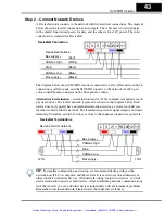
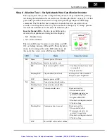
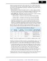
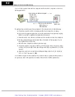
Inverter Status LEDs
– The two status LEDs on the
inverter’s front panel are to the right of the Stop key.
• MS – Module Status
• NS – Network Status
The status LEDs may be green or red, and may or OFF,
ON, or flashing between OFF and ON. The table below
shows how to interpret the status LED indications. (At
this point, the correct status is MS=green, NS=OFF.)
LED
Color
Status
Corrective Action
MS
Green
Normal power-ON status
—
Flashing Green
Inverter in standby state
—
Red
Fatal error (trip E11 or E12)
•
Confirm electrical noise level
is acceptable
•
Replace inverter
Flashing Red
Trip condition (non-fatal)
Look up error code in manual
Chapter 6, press Stop/Reset
OFF
Inverter power is OFF
—
NS
Green
Connected to network/online
—
Flashing Green
Connected to network/idle
—
Red
Critical network error
Check network for:
•
Disconnected cable
•
Termination resistor not
present / wrong value
•
Duplicate MAC IDs
•
Baud rate settings mis-match
•
Cable too long
Flashing Red
Communications time-out
Check network for:
•
Disconnected cable
•
Termination resistor not
present / wrong value
•
Baud rate settings mis-match
•
Cable too long
OFF
Power OFF or DeviceNet offline
—
Hz
POWER
A
RUN
PRG
RUN
STOP
RESET
MS
NS
HITACHI
FUNC.
STR
1
2
5 0.0
Artisan Technology Group - Quality Instrumentation ... Guaranteed | (888) 88-SOURCE | www.artisantg.com


