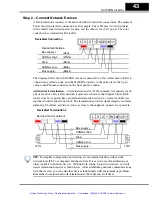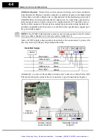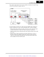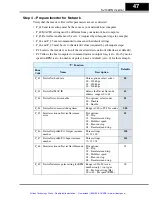
Network Control and Monitoring
56
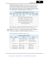
Polled I/O Data Map, Inverter Inputs
– The polled I/O for the inverter maps to four
words (16 bits each) input data, and four words output data. In this section, we are
concerned with the four words the host computer uses to control the inverter.
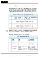
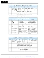
The following Polled I/O table shows how the host computer’s control bits and reference
data (output freq. / accel / decel) are organized. Word 0 (lower byte) contains discrete
(individual) bits (used as flags). Data words 1, 2, and 3 contain values (used as scalar
numbers). When the network is active, polled I/O data is automatically updated on each
network scan.
NOTE:
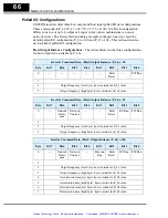
P_46 = 20 and P_46 = 21 settings provide additional consumed data configura-
tions (not used in this example). See “Polled I/O Configurations” on page 66.
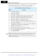
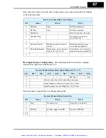
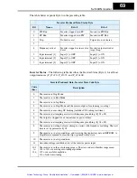
The following table defines individual bits of the control byte.
Inverter Consumed Data, (Host) Output Instance (P_46) = 100
Byte
Bit 7
Bit 6
Bit 5
Bit 4
Bit 3
Bit 2
Bit 1
Bit 0
0
—
Network
Refer-
ence
Network
Control
—
Free run
Stop
Fault
Reset
RV Run
FW Run
1
—
2
Output frequency (low byte), host override for F_01 value
3
Output frequency (high byte), host override for F_01 value
4
Acceleration time (low byte), host override for F_02 value
5
Acceleration time (high byte), host override for F_02 value
6
Deceleration time (low byte), host override for F_03 value
7
Deceleration time (high byte), host override for F_03 value
Inverter Consumed Data, Control Byte
Bit
Name
Bit = 0
Bit = 1
0
FW Run
Stop
FW Run command
1
RV Run
Stop
RV Run command
2
Fault Reset
—
Reset the inverter, clear trip
3
Free Run Stop
—
Cause motor to free run
(coast) and stop
4
—
—
—
5
Network Control
Run/Stop control is local to
inverter
Run/Stop control is from
network host polled I/O
6
Network Reference
Output freq. / accel / decel is
from F_01, F_02, F_03
Output freq. / accel / decel is
from network host polled I/O
7
—
—
—
Artisan Technology Group - Quality Instrumentation ... Guaranteed | (888) 88-SOURCE | www.artisantg.com


