


SJ100DN Inverter
43
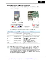
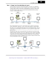
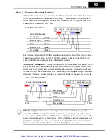
Step 2 – Connect Network Devices
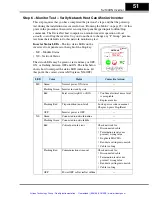
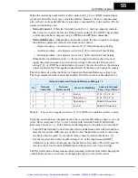
A DeviceNet node connects to the network with five electrical connections. The diagram
below shows the inverter connection as an example. The cable uses two twisted pairs
with a shield. One twisted pair is for data, and the other is for +24V power. The color
code shown is standard for DeviceNet.
The diagram below shows SJ100DN inverters connected to a DeviceNet network. Each
connection is called a node, and the SJ100DN connects to the network via the 5-pin,
color-coded Phoenix connector on the front panel as shown.
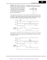
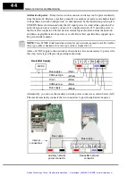
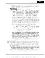
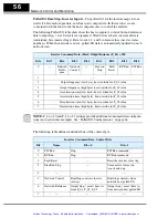
Add network termination
– A termination resistor (121
Ω
nominal) is required at each
physical end of a DeviceNet network (segment) as shown in the diagram below. Each
device does not typically have an internal termination resistor, as several such devices
together would overload a network. The terminations provides signal integrity and noise
immunity. Therefore, add two resistors as close to the endpoint connectors as possible.
TIP:
To simplify configuration and startup, we recommend starting with just the
network host (PLC or computer) and the inverter. It is easier to resolve addressing or
other conflicts with fewer devices. With network wiring for just two devices, you will
need a termination resistor at both devices. After establishing network communications
with the inverter, you can add other devices individually with a minimum of problems.
Remember to maintain network termination at the endpoints at all times.
L 3
1
2
P24 CM2 12 11
DeviceNet Connection
CANbus High
CANbus Low
Drain
Bus supply –
Bus
DeviceNet interface
(Bare)
(Red)
(White)
(Blue)
(Black)
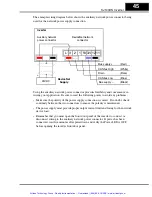
L 3
1
2
P24 CM2 12 11
DeviceNet Terminations
CANbus High
CANbus Low
Drain
Bus supply –
Bus
121
Ω
121
Ω
Device at end of network
Artisan Technology Group - Quality Instrumentation ... Guaranteed | (888) 88-SOURCE | www.artisantg.com


