background image

 Standard Communication Functions  6-7

Assume that the printer is ready for printing.

1

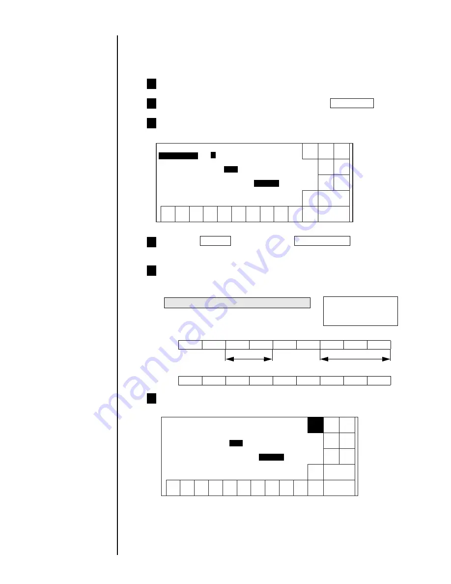
6.3.3 Print Condition Transmission

 The procedure for changing the character height from "99" to "90" and change

the character width from "050" to "000."is shown in the example below.

From the "Print description" screen, press Print spec .

2

You can see a character height setting of 99 and character
width of "050" entered.

3

Transmit character height data and character width data from
the external device to the IJ printer.

5

Shows text data between STX and ETX

Transmission data

ESC Header

9

0

ESC Header

0

0

0

Transmission code

1BH

30H

39H

30H

1BH

31H

30H

30H

30H

Character width

Character height

Number of character
 height digits
In the case of "2 digits"

Shut
down

Manual

Back


Prev.

dis-

paly

Next

dis-

paly

Decre-
ment

Incre-
ment

1

2

3

4

5

6

7

8

9

Print specifications

Status: Ready

0

[    9 ] (0-99)

Character width

[ 0 5 0 ] (0-199)

Character orientation [ 0 ] (0:          1: ABC 2:         3:        )
  (Arrow: Printing direction)        


Printing method

  2   (1:single scan 2:                   )  

9

Character height

Interlaced

ABC

The character height setting then changes to "90".
The character width setting then changes to "000."

6

Shut
down

Manual

Back


Prev.

dis-

paly

Next

dis-

paly

Decre-
ment

Incre-
ment

1

2

3

4

5

6

7

8

9

Print specifications

Status: Ready

0

Character height

[ 9 0 ] (0-99)

Character width

[ 0 0 0 ] (0-199)

Character orientation [ 0 ] (0:          1: ABC 2:         3:        )
  (Arrow: Printing direction)        


Printing method

  2   (1:single scan 2:                   )  

Interlaced

ABC

Show

cursor

Press the Manual  key then press Online/Offline key.

The status then changes from "off-line (Com=0)" to "on-line (Com=1)".

4

Com=1

ABC

ABC

ABC

ABC

Summary of Contents for PH

Page 1: ...aintenance procedures and other detailed handling procedures of the Hitachi IJ Printer Model PH If the printer is improperly handled or maintained it may not operate smoothly and may become defective or cause an accident It is therefore essential that you read this manual to gain a complete understanding of the printer and use it correctly After thoroughly reading the manual properly store it for ...

Page 2: ...CAUTION category is ignored serious results may occur depending on the situation After the manual has been read it must be stored in such a location that all printer operation personnel can refer to it at all times All the instructions set forth in this manual are important and must therefore be observed without fail Pictograph Examples The symbols are used to indicate precautions including those ...

Page 3: ...end of the print head When the printer is ready to print a high voltage approximately 6 kV is applied to the deflection electrode section in the print head Exercise caution to avoid electric shock injury and fire Do not remove the outer covering A high voltage is applied to some sections of the printer Exercise caution to avoid electric shock and injury Use an AC voltage of 100 to120 V or 200 to 2...

Page 4: ...e the printer is engaged in printing or just turned on press the Main power switch to turn off the power The printer must be managed in compliance with all appropriate regulations Read and understand the appropriate Material Safety Data Sheet MSDS before using any ink or makeup Use Hitachi approved consumables and periodic replacement parts Using products that are not designated by Hitachi could c...

Page 5: ... no vapors remain inside Should you find a leak of ink or makeup inside the printer while the printer is running or being maintained wipe it off promptly with wiping paper or something similar Then with the maintenance cover open stop the printer power it down and repair the leak Continuing operation with a leak of ink or makeup will cause an anomaly resulting in abnormal printing Ink and makeup a...

Page 6: ... be stored as flammable liquids Storage must comply with local regulatory requirements Consult the appropriate regulatory agency for further information If extraneous noise enters the printer it may malfunction or break down For maximum noise immunity observe the following installation and wiring precautions Ensure that 100 to 120 VAC or 200 to 240 VAC power cables are not bundled with other power...

Page 7: ...imits for a Class A digital device pursuant to part 15 of the FCC Rules These limits are designed to provide reasonable protection against harmful interference when the equipment is operated in a commercial environment This equipment generates uses and can radiate radio frequency energy and if not installed and used in accordance with the instruction manual may cause harmful interference to radio ...

Page 8: ...s 1 22 1 5 1 Wiring Precautions 1 22 1 5 2 Overview 1 24 1 5 3 Connection of various signal 1 28 1 5 4 Using the Ready Output Selector Switch 1 44 2 Basic Operating Procedures 2 1 2 1 Startup 2 1 2 1 1 Starting an operation 2 1 2 1 2 If a fault occurs at the beginning of an operation 2 4 2 1 3 Operations for Modifying the Setting Contents 2 7 2 2 Shutdown 2 10 2 3 Operating Scheme 2 12 2 3 1 Opera...

Page 9: ...g the Operating Environment 4 1 4 1 Managing the Operations 4 1 4 2 Setting the User Environment 4 3 4 3 Setting the Date and Time 4 7 4 4 Setting the Password 4 9 4 5 Controlling the Executable Functions 4 11 4 6 Confirming the Registered Software 4 13 4 7 Touch screen Setup 4 14 4 8 Printing Without Entering Sensor Signals 4 16 5 Auxiliary Function 5 1 5 1 Managing Created Print Data 5 1 5 1 1 C...

Page 10: ...haracter Transmission 6 37 6 4 9 Calendar Character Transmission Procedure 6 37 6 4 10 Calendar Conditions Transmission Procedure 6 38 6 4 11 On line Off line Transmission Procedure 6 39 6 4 12 Current Time Output Transmission Procedure 6 39 6 4 13 Count Character Transmission Procedure 6 39 6 4 14 Count Conditions Transmission Procedure 6 40 6 5 Communication Timing 6 41 6 5 1 Signal Timimg 6 41 ...

Page 11: ...Ink Tank 7 41 8 If a Warning Condition Fault Occurs 8 1 8 1 Indications Given When a Warning Condition Fault Occurs 8 1 8 2 On screen Message Descriptions 8 3 8 2 1 Fault messages 8 3 8 2 2 Warning messages 8 7 8 2 3 Other messages 8 8 8 3 Confirming the Warning Condition and Fault Occurrences 8 9 8 4 Remedial Action to Be Taken in the Event of a Printing Failure 8 10 9 Troubleshooting Guide 9 1 1...

Page 12: ... print head cleaning 7 Beaker with handle 1 451410 Used for print head cleaning ink replacement and other purposes 8 Wide mouth bottle 1 451126 To be used as a waste solution tank 9 Wiping paper 1 Used to wipe the print head after cleaning 10 Nozzle flat filter 75 1 451037 Spare part Recovery system filter 11 O ring P12 1 451214 Spare part For recovery system filter sealing 12 O ring SF7000 5 6 1 ...

Page 13: ...inage tube 1 451676 Used for ink replacement and filter replacement 17 Cable ties 2 For fixing a power cable 18 Protection sheet 1 3N4ZN 1646A For protection of operation panel Cable clamp Nozzle rubber seal Used for storage of One page sheet and nozzle rubber seal If you order items that attached with the main body tell up their item name and parts No One page sheet ...

Page 14: ...ental conditions temperature humidity dust etc determine the best replacement intervals in accordance with the obtained printings and replace all ink within the printer with new ink Ink type Replacement intervals operating hours or elapsed months whichever comes earlier Approximate operating hours Approximate elapsed months JP K26 600 to 1200 6 JP G27 600 to 1200 6 JP K27 600 to 1200 6 JP R27 600 ...

Page 15: ... into public sewer systemsor elsewhere Waste disposal must comply with all apropriate regulations Consult the appropriate regulatory agency for further information WARNING 4 Ink differences and handling precautions The ink which you can use differs with areas Please confirm ink which you can use to each area s distributors Notice Differences 1 Ink type Applicable makeup ink Operating temperature r...

Page 16: ... if it is exposed to ultraviolet rays after printing Its hardenability varies with the printed matter material and surface condition roughness and presence of deposits printed matter temperature time interval between printing completion and ultraviolet radiation employed ultraviolet radiation device and other factors You should confirm the ink hardenability under the employed operating conditions ...

Page 17: ...ays indicate that heating has not been performed 6 Change of color tone will vary depending on material of printed matter shape surface condition and hue Especially when printing is done with dark color change may not be clearly indicated 1 Change of color is caused by seeping of dye So in cause before change of color the elution test standard for appliance and container specified by food hygiene ...

Page 18: ...nk uses organic color whose specific gravity is low for pigment It can be used in the same way as dye ink when periodical maintenance is performed 1 Cautions during normal operation Ink Yellow Surface of Ink Settled pigment Dark yellow 2 Caution when continuously running for 24 hours a day for more than a month When continuously running the printer for 24 hours without stopping it even once a day ...

Page 19: ...according to the ink to be used and ambient temperature of the place for the operation It is different depending on major components of a solvent of the ink Storage temperature Estimated term of possible shutdown 3 Operating time per operation 0 T 35 3 weeks 10 days 1 to 4 hours 35 T 40 2 weeks 7 days 1 hour 40 T 45 1 week 5 days 1 hour 1 2 1 Maximum period possible to be continuously shut down wi...

Page 20: ...eup ink After cleaning thoroughly wipe the print head with wiping paper and allow it to dry It is necessary to wipe and dry the nozzle charging electrode deflecting electrode mounting base and fringe of the gutter While the print head is wet do not orient its end upward If you use the JP K60 JP F63 JP K68 JP E78 ink you must allow the printhead to dry firmly before running because the ink is not e...

Page 21: ...the surface of the mounting base and creepage is caused In this case remove the plus deflecting electrode and wipe the mounting surface clean with wipe paper to which an makeup ink is applied In addition remove the charging electrode and wipe the orifice plate surface clean likewise When printing is frequently performed or an space between the print material and the print head is small ink splashe...

Page 22: ...No cleaning stop key within the control menu 2 Press OK 3 The ink stop confirmation message appears 1 Do not use the Shut down key to stop an operation more than two successive times 2 If you stop an operation with the No cleaning stop key immediately initiate ink ejection If such a condition is allowed to continue the nozzle may become stuck with the ink causing the ink beam to be bent or the noz...

Page 23: ...on of operating hours hours Operating hours 5 4 3 2 1 0 10 20 30 40 50 Ambient temperature 1 Example If you use JP K67 ink at 20 the IJ printer must eject the ink for one hour or more 2 The makeup ink which enter in the IJ printer by automatic cleaning is evaporating naturally and then the ink becames initial state Caution when daily operating time is relatively long Since the IJ printer jets ink ...

Page 24: ...derable amount of paper powder or other dust exists When the printing distance is short so that the end of the print head is splashed with ink When you use the JP K60 JP F63 JP K68 JP K70 JP T71 JP K77 JP E78 JP K81 JP K84 JP B85 ink 2 Air purging procedure Introduce clean dry air into the print head air purge connection port Rc 1 8 PT 1 8 screw in the rear of the printer main body at a pressure o...

Page 25: ...ontrolled to maintain optimum concentration for print 2 If fault occurs in the viscosity meter which is used to control ink concentration take care of the following points There are three types of faults for viscometer Viscometer Temperature Sensor Fault Viscosity Reading Instability and Viscosity Readings Out of Range When Viscometer Temperature Sensor Fault occurs the unit will enter fault stop ...

Page 26: ...on sheet is provided to protect the screen display of the IJ printer This is used to prevent the screen display from becoming dirty scratched etc 1 Installation of Protection Sheet Clean all dirt debris ink etc from the panel surface Use a paper wipe etc soaked in water or makeup to wipe the display clean Install the protection sheet after the panel surface has dried Peel off the removable paper f...

Page 27: ...nnection of signals Power switch Push ON push OFF altanative Connection tube 4m Print head This section performs printing Handle Air purge connection port See Section 1 2 6 Print head air purge Exhaust duct connection port Attention to the instruction of IJ printer Stainless steel of the main body has the character it not to be easy rust but it is a possibility that rust is generated when leaving ...

Page 28: ...nent Names and Functions 1 17 1 3 2 Main body internal parts arrangement Ink reservoir Maintenance cover Ink filter Makeup ink reservoir Main ink tank Operation panel cover Various signals connecting portion ...

Page 29: ...1 18 Component Names and Functions 1 3 3 Print head Print head cover lock thumbscrew Nozzle Plus deflection electrode Gutter Minus deflection electrode Charge electrode ...

Page 30: ...d makeup ink and replacement of filter 1 4 Installing Precautions Ensure that there is no flame or arc generating device around the printer The ink and makeup are both flammable and may cause fire Fire can be generated by matches lighters cigarettes heaters stoves gas burners welders grinders and static electricity Arcs may be generated from open type relays switches and brush motors Before handli...

Page 31: ...ad IJ printer main body Main body installation surface 1 5m Upward printing Lateral printing Downward printing Print head cable included 1m 10 When using the printer for upward or lateral printing ensure that the rising print head cable upper end is positioned not more than 0 5 m above the print head Print head cable Bend R 0 5m Print head 11 If you fixed the print head ensure that the minimum ben...

Page 32: ...ubstance such as iron the cover switch will malfunction resulting in an Cover Open error This you must only use nonmagnetic resins or metals for fixing the print head 15 In the case of carrying the printer proper put in your hands from the direction of the arrow in the drawing below ...

Page 33: ...ally isolate the print target detector print head stand and IJ printer body from other machinery and equipment conveyor etc Separate the print target detector wiring from other power lines Perform that all electrical wiring connections and grounding comply with applicable cords When erroneous operation was caused by noise etc use a dedicated ground 1 2 3 4 5 Conveyor Motor power supply line Print ...

Page 34: ...current is also diverted to signal ground and the PC boards may be damaged For this reason when performing welding work near the IJ printer proceed as follows Method Be sure to insulate the printhead and IJ printer frame to keep the welding current from flowing to the control section of the printer and to make a separate ground connection for the printer If this method is used welding work becomes...

Page 35: ...int printing print completed stop printing online and remote signals φ4 5 to 10 M16 For ready fault warning φ4 5 to 10 M16 For external communication φ3 5 to 10 indicates a tightening nut Power switch Use cables with an outside diameter within the range specified above Firmly tighten the lead in port lock nut In addition do not bundle weak electric system and strong electric system cables together...

Page 36: ...l ground 14 Run Input 15 Reset Clear Input 16 Stop Input 17 Online Output Applicable cable size AWG26 to 14 φ0 4 to 1 6 Wire covering to be stripped 9mm Layout of connectors for connection External connection terminal block 1 TB1 External connection terminal block 2 TB2 Communication connector SW1 1 The supplying power capacity for print target detector and encoder is up to 100mA in total Push Wir...

Page 37: ... NO 6 COM 7 Warning NC 8 NO 9 COM NOTE NC Normally closed NO Normally open COM Common Terminal specification M4 Connection to the external communication RS 232C connector Pin number Name Input Output Remarks 1 NC Unconnected 2 RD Input 3 SD Output 4 NC Unconnected 5 SG Ground 6 NC Unconnected 7 NC Unconnected 8 NC Unconnected 9 NC Unconnected ...

Page 38: ... printer proper Remove the claw and divide it Tie the seal around the outside of the cable as in the drawing Tie the seal so that there will be no clearance between it and the cable seal block Mount it on the printer proper by using a reversed procedure Remove the tightening nut Put the cable through as in the drawing Tighten the tightening nut Tighten the tightening nut securely by using a tool 1...

Page 39: ...er supply To conveyor TB2 1 2 3 2 3 contact Ready state Closed Other than above Open b When using the NC contact break contact 1 3 contact Ready state Open Other than above Closed For both the NO and NC contacts the maximum capacity is 30 VAC 0 5 A or 30 VDC 1 A If any load having a greater capacity is used furnish a separate relay in between Further if a motor relay or other inductive load is emp...

Page 40: ... output The following describes the wiring of the signal that is outputted to the outside for the purpose of indicating that the IJ printer is in the fault mode a When using the NO contact make contact Status indicator lamp or the like Power supply TB2 5 6 contact Fault state Closed Normal state Open b When using the NC contact break contact Status indicator lamp or the like Power supply TB2 4 6 c...

Page 41: ... contact Status indicator lamp or the like Power supply TB2 7 9 contact Warning state Open Normal state Closed For both the NO and NC contacts the maximum capacities of the fault and warning condition outputs are 30 VAC 0 5A or 30 VDC 1 A If any load having a greater capacity is used furnish a separate relay in between Further if a motor relay or other inductive load is employed a counterelectromo...

Page 42: ...3 4 Print target detector a When a dedicated power supply is not used If the print target detector current consumption is not more than 80 mA no dedicated power supply is required because adequate power can be supplied from the IJ printer built in power supply In such a situation make wiring connections and perform setup as indicated below i Print target detector wiring method Use a print target d...

Page 43: ...e table below Print target detection signal Printing operation Time of preparing for printing ON Printing Time of preparing for printing Printing interval OFF 3 ms minimum Print start delay adjustment 0 ON OFF Switch is black 12V c Relationship between print target detection signal and printing operation 3 ms minimum Printing Nozzle size Approximate Time 65µm 10 ms The required time is precisely c...

Page 44: ...ore Maximum drive current 12 mA or more Residual voltage 2 V or less Leak current 0 1 mA or less Drive method Open collector When the input is ON While the IJ printer is in the ready state it does not make prints even if the print target detector turns ON However if any printing operation is being performed it does not come to a halt When the input is OFF While the IJ printer is in the ready state...

Page 45: ...A or more Leak current 0 1 mA or less Supply voltage 12 VDC Current consumption 80 mA or less b Setup i From the print specifications screen specify whether or not to enable the product speed matching feature See Section 3 4 Setting Character Height and Character Orientation ii See the table below and set up switch SW2 on the EZJ95 board I O in accordance with the rotary encoder output type Switch...

Page 46: ... exceeds 80 mA or a 24 VDC type rotary encoder is used furnish a dedicated power supply and make wiring connections as indicated below For totem pole output DC dedicated power supply Rotary encoder V GND V GND Signal TB1 For open collector output DC dedicated power supply V GND V Rotary encoder TB1 1 2 3 4 DC12V OFF ON ON OFF DC24V OFF OFF ON OFF SW2 Supply voltage e Setting the rotary encoder pul...

Page 47: ...t count character width setting 1 x ink drop use percentage printing scan count maximum value kHz Equation 2 The excitation frequency f value varies with the ink type employed Ink type Excitation frequency 65μm Nozzle Machine JP K26 68 9kHz JP K27 68 9kHz JP R27 68 9kHz JP G27 68 9kHz JP K28 68 9kHz JP K33 74 0kHz JP K60 68 9kHz JP K61 68 9kHz JP K62 68 9kHz JP F63 68 9kHz JP T64 68 9kHz JP K65 68...

Page 48: ...on factor and calculated using the following equation Number of speed synchronization signal pulses kHz printing scan count kHz pulse rate division factor 1 n Equation 3 The pulse rate division factor l n must be set up from the print specifications screen See Section 3 4 Setting Character Height and Character Orientation If the calculation result derived from Equation 2 is smaller than the printi...

Page 49: ...ting signal OFF ON OFF ON Print object detection signal 100 ms min Ensure that the interval between reciprocative printing signal changeover ON OFF or OFF ON and print object detection signal input is at least 100 ms 1 5 3 8 Print output signal output The following shows the wiring of the signal that is outputted when a printing operation is being conducted or completed by the IJ printer a Wiring ...

Page 50: ... corresponding to the run state operation keys of the IJ printer Run Stop fault Clear and Deflection Voltage Control switchover between a standby state and a ready state by means of external switches contact signals or something similar a Input specifications Make inputs by no voltage contacts In the case of no contact use terminals that satisfy the following requirements Withstanding voltage 12 V...

Page 51: ...not be accepted The time t3 from an input of high voltage ON OFF signal till a change of statue is 3 seconds or less Standby Print Enable t4 is 100ms or less Print Enable Standby For turning on the high voltage ON OFF signal the status must be confirmed beforehand If the high voltage ON OFF signal is turned on by mistake during printing this printing which may be in progress is aborted and the pri...

Page 52: ...ut into a pause by turning on the stop signal turn off the power supply The time from turning on the stop signal till a pause status is about 3 minutes The time t6 from an input of stop signal till a change of status is 100 ms or less Cautions 1 When using key inputs you must check each input However when inputting external signals the equipment executes processing in accordance with instructions ...

Page 53: ...ermissible current is 50 mA Vd DC30V 1 5 3 10 Online signal output Connection of signals outputted to the outside when the IJ printer is online a Wiring Load TB1 17 13 Online GND If a relay solenoid or other inductive load is employed connect a counterelectromotive force generation prevention diode in parallel with the load The load circuit is for DC only It cannot be used with an AC load Output s...

Page 54: ...d Attaching screw inch screw Substrate side connector 9 pin D sub connector plug IJ printer Transmission Reception Cable length maximum 5m SD RD SG Output 3 2 5 Input External device RD SD SG FG Do not connect any signal other than 2 3 and 5 since it is not used Do not bundle it together with heavy current signals inside and outside the equipment so that it will not be influenced by noise from a h...

Page 55: ...sed the ready output signal is disabled The path between TB2 terminals 1 and 3 opens and the path between TB2 terminals 2 and 3 closes as shown in the table at right regardless of whether the IJ printer is ready 1 5 4 Using the Ready Output Selector Switch The ready output selector switch SW1 is used to enable or disable the ready signal output see under 1 5 3 1 Ready output signal Ready state Not...

Page 56: ...Emergency Procedures CAUTION Press the power ON OFF switch to turn ON the power 1 Press The following print description screen opens The current operating status is indicated see Section 2 3 2 Status for details The printings are described It takes about 50 seconds for the above screen to open Verify that the printing contents are input correctly For print description input see Section 3 Editing P...

Page 57: ...ter a holiday complete the print head cleaning procedure in the same manner as for shutdown see Section 2 2 Shutdown and Section 1 2 Usage Precautions 2 Press the Start up key Press the Ready key Entering a run signal executes the same action See Section 1 5 3 9 Input for remote con trol signals Com 0 Start up Menu Ink Jet Startup Confirmation The ink jet will be turned ON Solution To turn the ink...

Page 58: ...ginning of an operation When the ink jets out it may momentarily scatter and stain paper However this does not indicate any abnormality at all Wait until the status changes from Starting to Ready If any startup fault occurs see Section 2 1 2 If a fault occurs at the beginning of an operation When the temperature is low below 20 or so it takes slightly longer for the printer to become Ready for pri...

Page 59: ...ng screw 2 Loosen the screw Print head cover Pull out No cleaning stop Stops ink ejection without cleaning Standby Switches between the ready for printing state and standby state Manual Control Menu Online Offline No cleaning stop Manual Shut down Standby Cancel Press the Manual key Manual Control Menu Press the No cleaning stop key Press the OK key Shutdown Process Confirmation Shutdown will stop...

Page 60: ...er to Section 1 2 3 Print head cleaning 3 Orifice plate Charge electrode Deflection electrode Gutter Mounting base Area to be cleaned Cleaning bottle Beaker With wiping paper thoroughly wipe the makeup ink away from the parts mounting base included surfaces and then allow them to dry With the print head cover left removed press the Manual key to display the control menu Press the Start up and Read...

Page 61: ...he ink stream position wear protectors goggles and mask If the ink or makeup ink should enter your eyes or mouth immediately flush with warm or cold water and see a physician Before ejecting the ink ensure that there is no person in the direction of ejection The end of the print head must be placed in a beaker or the like WARNING Install the print head cover If the Cover open fault is indicated pr...

Page 62: ... Maintenance work Touch screen setup Standby Stop Auxiliary function Manage messages Create user pattern Copy data Memory card Printer As the Apply key appears if you modify the setting contents be sure to press the Apply key after you have completed modification 1 Operation in the Ready state Procedure Display the cursor and keyboard Enter a value Reflect the value in printing 1 2 3 You can displ...

Page 63: ...creen or the confirmation screen Entering a deflection voltage ON OFF signal executes the same action See Section 1 5 3 9 Input for remote control signals See Section 1 5 3 1 Ready output signal No cleaning stop Stops ink ejection without cleaning Standby Switches between the ready for printing state and standby state Manual Control Menu Online Offline No cleaning stop Standby Cancel No cleaning s...

Page 64: ...l setup When making a 1 line print the single scan control predominates even if you perform steps 1 through 3 Precautions to be observed when changing the printings print format or print line setup data 1 2 3 1 3 1 3 2 Ejecting the ink using the control menu This feature is used to eject the ink from the nozzle with no intention of printing for maintenance purposes only Press the Start up key to m...

Page 65: ...er Mounting base Area to be cleaned Cleaning bottle Beaker 1 With wiping paper thoroughly wipe the makeup ink away from the parts mounting base included surfaces and allow them to dry 2 The nozzle rubber seal is effective in assuring orifice plate dryness and preventing dust buildup For increased smoothness in later printer startup it is recommended that you install the nozzle rubber seal between ...

Page 66: ... rubber seal has been incorporated at the factory prior to shipment Remove the nozzle rubber seal at the time of printer installation test run adjustment 2 The nozzle rubber seal is effective in preventing orifice plate drying and dust accumulation When shutting down the printer it is recommended that you set the nozzle rubber seal between the orifice plate and charge electrode to assure smoothnes...

Page 67: ...it message Print line setup Save message Select message Calendar conditions Count conditions Input key Screen name Back Back Back Back OK OK Save message Print line setup Calendar conditions Count conditions Edit message OK or Print format Print specification s Maintenance Auxiliary function Menu Menu Select messag e Power OFF Power ON Back Calendar Count Calendar Count ...

Page 68: ...er changes from the inactive state to the standby state 5 Ink heating Start up in process with the ink being heated 6 Drop adjust Period during which ink particles are not properly charged in the standby state 7 Cover open Period during which the nozzle head cover is open in the standby state 8 Service Circulation control process for maintenance task execution 9 Fault State in which a fault exists...

Page 69: ...shows either Stop Standby or Ready Print description Column1 Column2 Column3 Start up Menu Print line setup Edit message Print format Print spec Select message Save message Status Stop Com 0 Print description Column1 Column2 Column3 Menu Print line setup Edit message Print format Print spec Select message Save message Status Stop Com 0 U 1 S 5 E 0 B 7 Y 0 7 1 M 5 F G 9 D A 0 0 T 7 E The print desc...

Page 70: ...characters Print spec is common for all print items Select the Print line setup Print format Edit message and Print spec screens from the menu and set them step by step Allocate each item into appropriate lines and columns to match the print descriptions The lines can be set up to 4 The function printable lines and character sizes are different depending on the model type For more details see 11 1...

Page 71: ...ming to the character size conditions will be printed as spaces NOTICE Performing setup on an individual column basis The entered number of lines is set for designated columns When the number of lines is increased new lines are added to the lowermost line position When the number of lines is decreased the lowermost lines are deleted accordingly No changes are acceptable if the number of print item...

Page 72: ...Print line setup type Overall column setup Individual column setup 1 line 2 lines 3 lines 4 lines Insert column Delete column OK Print line setup Column1 Column2 Column3 Shut down Manual Cancel Status Ready Print line setup type Overall column setup Individual column setup 1 line 2 lines 3 lines 4 lines OK Print line setup Column1 Column2 Column3 Shut down Manual Cancel Status Ready Press OK You a...

Page 73: ...Edit message Print format Print spec Select message Save message Com 0 Print line setup type Overall column setup Individual column setup 1 line 2 line 3 line 4 line Insert column Delete column OK Print description Column1 Column2 Column3 Shut down Manual Count reset Status Ready Print line setup type Overall column setup Individual column setup 1 line 2 lines 3 lines 4 lines Insert column Delete ...

Page 74: ... pattern 5 5 5 8 5 7 9 8 9 7 7 10 12 16 18 24 24 32 Special character 5 8 9 8 7 10 12 16 18 24 24 32 Arabic character 5 8 12 16 18 24 24 32 The available functions and printable line count and character sizes vary from one model to another See Section 11 1 Printer Specifications For size changeover between 7 10 and 9 8 see Section 4 2 Setting the User Envi ronment For dedicated charac ter varietie...

Page 75: ...8 Code set B All Alphabets numerals symbols and FNC1 Code set C 0 to 9 FNC1 Bar code type changes are simultaneously applied to all items for which bar code setup has been cimpeleted For DM and Code 128 number of barcodes which can be set is four When multiple barcodes are to be set insert print item to which no barcode has been set between them For Code 39 ITF NW 7 EAN 13 DM and Code 128 barcode ...

Page 76: ...the EAN 13 printing item 1 line 2 Set character size 12 16 18 24 or 24 32 Set as shown below for print item to which DM is to be set i Number of lines 1 line ii Character size 5 8 12 16 18 24 Set barcode type to DM on the print format screen and select the size Notice of DM code is used Input characters within the specified digit number for print item to which barcode has been set If characters ex...

Page 77: ... Operations for modifying the setting contents See Section 2 1 3 Operations for modifying the setting contents Prev item Print format Manual Status Ready Next item Prev dis play Next dis play Back 1 2 3 4 5 6 7 8 9 0 Decre ment Incre ment Line spacing 0 dots 0 2 Inter char space 1 dots 0 3 Increased width 1 times 1 9 5x5 1 Character size Prev item Print format Manual Status Ready Next item Prev di...

Page 78: ...r Increment key 5 Press Apply 6 Press Back twice You are then returned to the Print description screen 7 Cursor will move to the line you touched Selected item on the cursor positioned line can be changed by touching Prev item Print format Manual Status Ready Next item Prev dis play Next dis play Back 1 2 3 4 5 6 7 8 9 0 Decre ment Incre ment 12x16 4 Character size Prev item Print format Manual St...

Page 79: ...ard for inputting Code 39 will be displayed 7 Press 1 2 3 4 5 6 7 8 9 0 8 Press Apply 9 Press Back You are then returned to the Print description screen 10 Edit message Manual Status Ready Back 1 2 3 4 5 6 7 8 9 0 Show cursor Insert Delete ABC 123 Sign Spe cial Space Shift Column1 Column2 Column3 Shut down ABC 123 Sign ...

Page 80: ...st line of the first column 2 Operation when chang ing the alphanumeric keyboard to that of QWERTY key allocations See 4 7 Touch Screen Setup Print description Column1 Column2 Column3 Shut down Manual Menu Print line setup Edit message Print format Print spec Select message Save message Status Ready Com 0 Message name SAMPLE1 2015 07 07 11 15 Edit message Shut down Manual Status Ready Back Q W E R...

Page 81: ...iption screen 5 Type of alphameric character standard character Refer to 6 4 6 Code tables Print description Column1 Column2 Column3 Shut down Manual Menu Print line setup Edit message Print format Print spec Select message Save message Status Ready Com 0 Message name SAMPLE1 2015 07 07 11 15 A BC ...

Page 82: ...in the third line of the first column From the Print description screen press Edit message 1 The Edit message screen then opens 2 Press Special The special input keyboard then appears 3 Operations for modifying the setting contents See Section 2 1 3 Operations for modifying the setting contents The Arabic input be unable to do in Simple Chinese Menu Print line setup Edit message Print format Print...

Page 83: ...ption screen 8 3 3 3 Printing special characters when special characters can be input 1 Overview Enter them from the special character keyboard 保証 Edit message Status Ready Column1 Column2 Column3 保証 Show cursor Manual Shut down ABC 123 Sign û ü ì ë ê é è ä ã â á à ô ó ò ï î í ß œ ñ ç æ ú ù ö õ Shift Λ Shift Û Ü Ì Ë Ê É È Ä Ã Â Á À Ô Ó Ò Ï Î Í Œ Ñ Ç Æ Ú Ù Ö Õ Shift Λ Shift Year Month Day Hour Minu...

Page 84: ...n character size 5 5 Φ Χ Κ Ι Θ Η Ζ Ε Δ Γ Β Α Π Ο Ξ Ν Μ Λ Ω Ψ Υ Τ Σ Ρ Shift Λ Shift φ χ κ ι θ η ζ ε δ γ β α π ο ξ ν μ λ ς ω ψ υ τ σ ρ Shift Λ Shift П Р Ж Ё Е Д Г В Б А М Л К Й И З Х Ц Ф У Т С О Н Shift Λ Shift Я Ю Э Ь Ы Ъ Щ Ш Ч Џ Ћ Њ Љ Ј Ђ Shift Λ Shift п р ж ё е д г в б а м л к й и з х ц ф у т с о н Shift Λ Shift ...

Page 85: ...Save message Edit message Shut down Manual Status Ready Back Show cursor Insert User pat tern Delete ABC 123 Sign Column1 Column2 Column3 A BC U S E B Y 5 7 7 M FG DA TE Spe cial Space Year Month Day Hour MinuteSecond Total Days JAN FEB Week number Day of Week Shift code Time count Count Kana Dedicated Calendar Count Arabic Y D M Y Press Year The first press of Year prints the last digit of the ye...

Page 86: ...ly the last digit of the month will be printed 6 Press The display then reads YY MM 7 Press Day twice The display then reads YY MM DD If you press Day only once only the one last digit of the day will be printed 8 Press Apply Press Back You are then returned to the Print description screen The print image area reads USE BY 15 07 07 10 9 ...

Page 87: ...displayed press Show cursor Operations for modifying the setting contents See Section 2 1 3 Operations for modifying the setting contents Cursor will move to the line you touched Menu Print line setup Edit message Print format Print spec Select message Save message Edit message Shut down Manual Status Ready Back Show cursor Insert User pat tern Delete ABC 123 Sign Column1 Column2 Column3 A BC U S ...

Page 88: ...Print line setup Edit message Print format Print spec Select message Save message Edit message Shut down Manual Status Ready Back Apply Insert User pat tern Delete ABC 123 Sign Column1 Column2 Column3 A BC D Y Spe cial Space Year Month Day Hour MinuteSecond Total Days JAN FEB Week number Day of Week Shift code Time count Count Kana Dedicated Calendar Count D E X X X X YY M Press Calendar Count The...

Page 89: ...AY 06 JUN 07 JUL 08 AUG 09 SEP 10 OCT 11 NOV 12 DEC JAN FEB F Subst rule setup Shut down Manual Status Ready Back Show cursor Dupri cate User pat tern Delete ABC 123 Sign Spe cial 01 EN 02 FEB 03 MAR 04 APR 05 MAG 06 GIU 07 LUG 08 AGO 09 SET 10 OTT 11 NOV 12 D I C JAN FEB G Press Apply 6 Press Back three times You are returned to the Print description screen The print image area reads 07LUG 2015 7...

Page 90: ...t message 1 The Edit message screen opens Press Column2 First line The cursor then moves to the second column 2 Menu Print line setup Edit message Print format Print spec Select message Save message Edit message Shut down Manual Status Ready Back Show cursor Insert User pat tern Delete ABC 123 Sign Column1 Column2 Column3 WEE U S E B Y Spe cial Space Year Month Day Hour MinuteSecond Total Days JAN...

Page 91: ...n 2 Menu Print line setup Edit message Print format Print spec Select message Save message Y Edit message Shut down Manual Status Ready Back Show cursor Insert User pat tern Delete ABC 123 Sign Column1 Column2 Column3 WEE U S E B Y Spe cial Space Year Month Day Hour MinuteSecond Total Days JAN FEB Week number Day of Week Shift code Time count Count Kana Dedicated Arabic Calendar Count K Y MM D D P...

Page 92: ...d Operations for modify ing the setting contents See Section 2 1 3 Operations for modifying the setting contents Menu Print line setup Edit message Print format Print spec Select message Save message D M Y Edit message Shut down Manual Status Ready Back Show cursor Insert User pat tern Delete ABC 123 Sign Column1 Column2 Column3 A BC U S E B Y Y M D M FG DA TE Spe cial Space Year Month Day Hour Mi...

Page 93: ...ress Apply 9 Press Back twice You are then returned to the Edit message screen 10 Cursor will move to the line you touched Selected item on the cursor positioned line can be changed by touching Shut down Manual Back Show cursor Prev item Next item Blank 1 2 3 4 5 6 7 8 9 0 0 0 0 0 Range 0 0 0 0 0 0 9 9 9 9 9 9 Jump from to 0 Count conditions Status Ready Prev dis paly Next dis paly User pat tern A...

Page 94: ...ZY0999 ZY1000 ZZ0999 ZZ0001 ZZ1000 Press Apply 3 Press Back twice You are then returned to the Edit message screen 4 2 Procedure for printing numbers from AA0001 AA1000 through AB0001 to ZZ1000 in the first line of the second row by incrementing the printed number by one after each printing 1 1 6 1 2 2 Procedure for printing numbers in increments of 5 from AA0001 through AA9986 in the first line o...

Page 95: ...ed characters can be combined with numbers ex Range 0 0 0 0 9 9 0909 Procedure for setting up registered characters as count values Change the values of the setup items on the Count conditions screen as follows This causes the cursor to move to the first line of the second row Value 00 Range 00 Update 000000 07 000001 Jump from increment 01 to Direction 1 ex Define the registered characters as fol...

Page 96: ...escription screen Count reset will be displayed 4 Print description Column1 Column2 Column3 Shut down Manual Count reset Menu Print line setup Edit message Print format Print spec Select message Save message Status Ready Com 0 Message name SAMPLE1 2015 07 07 11 15 0 0 1 A BC S E B Y 5 7 7 M FG DA TE 0 0 1 5 9 7 U Zero suppression 0 0 1 Enable Multiplier Shut down Manual Back Prev item Next item Bl...

Page 97: ... characters will change to 000001 6 Count Reset Confirmation The count value will be reset OK Cancel Print description Column1 Column2 Column3 Shut down Manual Count reset Menu Print line setup Edit message Print format Print spec Select message Save message Status Ready Com 0 Message name SAMPLE1 2015 07 07 11 15 0 0 1 A BC S E B Y 5 7 7 M FG DA TE 0 0 1 5 9 7 U 0 0 0 0 0 1 ...

Page 98: ... and execute printing with feet to meter converted 1 foot 0 3048 m Display Edit message screen and input count character 1 Display third screen of Count conditions and set 0 3048 to Multiplier 3 Edit message Shut down Manual Status Ready Back Show cursor Insert User pat tern Delete ABC 123 Sign Column1 Column2 Column3 CC Spe cial Space Year Month Day Hour MinuteSecond Total Days JAN FEB Week numbe...

Page 99: ...sion Enabled Initial value Multiplication result Printed result Note 0 0 0 0 0 1 0 3 0 4 8 0 3 0 4 8 0 0 0 0 0 2 0 6 0 9 6 0 6 0 9 6 0 0 0 0 1 0 3 0 4 8 0 3 0 4 8 0 0 0 0 1 1 3 3 5 2 8 3 3 5 2 8 3 2 8 0 8 2 9 9 9 9 9 3 9 3 6 9 9 9 9 9 Digit which can not be printed will be rounded off 3 2 8 0 8 3 9 9 9 9 9 6 9 8 4 1 0 0 0 0 0 Digit which can not be printed will be rounded off 9 9 9 9 9 8 3 0 4 7 9...

Page 100: ...characters 1 Overview Enter from the Arabic character keyboard The Arabic characters cannot be entered in character size 5 5 9 8 and 7 10 Entering an Arabic character will move the cursor to the left The Arabic input be unable to do in Simple Chinese ...

Page 101: ...tion and print start delay is described below The Print specifications first screen Character orientation Printing direction of characters can be set Settings and print results are as shown below 3 Setting Direction of transport Printing results 0 A B C a A B C 1 2 3 b 1 A B C a b A B C 1 2 3 2 a b 3 a b A B C 1 2 3 A B C 1 2 3 A B C 1 2 3 A B C A B C A B C 1 2 3 A B C 1 2 3 A B C 1 2 3 Direction ...

Page 102: ...e ink drop use percentage is 1 1 to 1 4 Perform overall column setup The format for the first item is then applied to all the other items so as to provide interlaced setup When making a 1 line print the single scan predominates even if you perform steps i through iii The Print specifications second screen 4 5 Sensor c Direction of transport Print target b Nozzle center a 0 0 2 3 Sensor c Direction...

Page 103: ...ncre ment 1 2 3 4 5 6 7 8 9 Print specifications Status Ready 0 0 0 1 10sec 0 none 1 999 Target sensor filter 1 1 2 until end of print Setup value 0 1 0 0 msec 0 9999 Ink drop use 0 1 1 1 1 16 Enter denominator 0 Target sensor timer time setup Target sensor timer You can specify the time for displaying a fault message when the sensor light is continuously blocked When the time of shielding the sen...

Page 104: ...eed printing for details Calendar offset Specifies whether the from today or offset from yesterday option is to be selected for calendar month year offset determination Day of week character Set the type of character to be printed for calendar day of the week Mon Tue Wed Thu Fri Sat Sun 1 to 7 1 2 3 4 5 6 7 A to G A B C D E F G Registered character C1 C2 C3 C4 C5 C6 C7 The last 7 chracters are use...

Page 105: ...rsor Cursor will move to the line you touched Cursor will move to the line you touched Selected item on the cursor positioned line can be changed by touching Shut down Manual Back Show cursor Prev dis paly Next dis paly Decre ment Incre ment 1 2 3 4 5 6 7 8 9 Print specifications Status Ready 0 5 0 99 Character width 0 0 0 0 199 Character orientation 0 0 1 ABC 2 3 Arrow Printing direction Printing...

Page 106: ...is 6 64 25 15 36 15 Round off the calculation results to the nearest whole number Print target Print target Repeat intervals Repeat count You can preset the number of repeat printing sequences to be performed while the sensor light is blocked If repeat printing is not needed select the number 0 Printing is performed in accordance with the repeat printing mode setup The relationship between repeat ...

Page 107: ...ess Apply 5 Press Back You are then returned to the Printing description screen 6 Cursor will move to the line you touched Shut down Manual Back Apply Prev dis paly Next dis paly Decre ment Incre ment 1 2 3 4 5 6 7 8 9 Print specifications Status Ready 0 Print start delay 0 0 0 0 scanning unit SC 0 9999 Reverse direction 0 0 0 0 character unit SC 0 9999 3 0 0 scanning unit SC 0 9999 Repeat count 0...

Page 108: ...26 11 03 27 11 03 27 11 03 28 11 02 28 11 03 27 11 03 28 11 03 28 11 03 29 11 03 01 11 03 31 11 04 01 11 04 01 11 04 02 12 01 28 12 02 27 12 02 28 12 02 28 12 02 29 12 01 29 12 02 28 12 02 29 12 02 29 12 03 01 12 01 30 12 02 29 12 02 29 12 02 29 12 03 01 12 01 31 12 02 29 12 02 29 12 02 29 12 03 01 12 02 01 12 02 29 12 03 01 12 03 01 12 03 02 12 02 02 12 03 01 12 03 02 12 03 02 12 03 03 12 02 27 1...

Page 109: ...otal Days JAN FEB Week number Day of Week Shift code Time count Count Kana Dedicated Calendar Count D M Y Y M D C CCC Shut down Manual Back Show cursor Prev item Next item Subst rules Decre ment Incre ment 1 2 3 4 5 6 7 8 9 0 Calendar conditions Status Ready Offset Substitution rules Zero suppression Substitution rules No 01 Press Month The cursor then moves to the Month field 4 Year Year 0 0 0 0 ...

Page 110: ...ming setup so that the time values between 00 and 11 are printed as AM and that the time values between 12 and 23 are printed as PM From the Print description screen press Edit message 1 The Edit message screen then opens Operations for modifying the setting contents See Section 2 1 3 Operations for modifying the setting contents Menu Print line setup Edit message Print format Print spec Select me...

Page 111: ...y Back A B C D E F G H I J Show cursor Dupli cate User pat tern Delete ABC 123 Sign Spe cial Space Shift 00 01 02 03 04 05 06 07 08 09 10 11 12 13 14 15 16 17 18 19 20 21 22 23 No 0 1 Type Hour Press A and M in sequence The cursor then moves to the next field 8 Press Duplicate The 01 field then reads AM The same result is obtained by pressing A and M in sequence 9 Shut down Manual Show cursor ABC ...

Page 112: ...ce 11 Repeat step 9 until the 23 field is covered The same result is obtained by pressing P and M in sequence instead of Duplicate To continue to perform substitution setup for year month day or minute switch to the target screen by pressing Next display or Previous display At each press of Previous display the screen changes in the day month year minute and hour order At each press of Next displa...

Page 113: ...urns you to the Print description screen Pressing Cancel causes the system to return to the Print description screen without saving the data 3 Operations for modifying the setting contents See Section 2 1 3 Operations for modifying the setting contents If the cursor is not displayed press Show cursor Menu Print line setup Edit message Print format Print spec Select message Save message Shut down M...

Page 114: ... of the previous contents continues Printing results change from the next printing 4 Operations for modifying the setting contents See Section 2 1 3 Operations for modifying the setting contents If the cursor is not displayed press Show cursor Menu Print line setup Edit message Print format Print spec Select message Save message Shut down Manual OK Show cursor Select message Status Ready Prev list...

Page 115: ...M or QM mode can be selected 1 No Item Conditions 1 Character size Character size of all print items is 5x7 2 Print line Number of lines in all columns is 2 lines or 3 lines 3 Line spacing line spaces in all columns are the same 4 Barcode Bar code is not set for any print items 5 Character orientation Set value of character orientation is 0 or 1 6 Ink drop use percentage Ink drop use percentage 1 ...

Page 116: ...nal ON Disable method1 Disable Print complete method1 Shut down Manual Back Show cursor Prev dis paly Next dis paly Decre ment Incre ment 1 2 3 4 5 6 7 8 9 User environment setup Status Ready 0 1 5x8 2 Char Size menu 2 1 1 2 9x8 3 9x7 Excitation V ref warning 1 0 0 Disable 1 2 Char Size menu 1 5x7 Enable 7x10 Set Character size to 2 5 x 7 Barcode to 0 none on the Print format screen 3 4 1 5x5 2 3 ...

Page 117: ...ecifications Status Ready 0 Character height 5 0 0 99 Character width 0 0 2 0 199 0 1 ABC 2 3 Arrow Printing direction Printing method 2 1 single scan 2 0 Character orientation Interlaced ABC Press Next Display twice The third page of Print specifications screen will appear 6 Set Ink drop use to 01 on the Print specifications screen 7 Shut down Manual Back Show cursor Prev dis paly Next dis paly D...

Page 118: ...formed Shut down Manual Back Apply Prev dis paly Next dis paly Decre ment Incre ment 1 2 3 4 5 6 7 8 9 Print specifications Status Ready 0 Product speed matching 0 0 1 Enable Pulse rate div Factor 0 0 1 1 1 1 999 Enter denominator 0 HM 1 2 QM Calendar offset 1 1 2 from today Day of week char 1 1 2 A G 3 User pattern 1 High speed print 1 7 NM Offset from yesterday Disable Press Apply 10 11 ...

Page 119: ...mmonly used with each item of print data which has been saved This is linked with Calendar time considering offset Shift code characters cannot be input in the same print item of any other calendar 2 Operating procedure Setting contents shown above example Press Edit message on the print description screen 1 Edit message screen will appear Menu Print line setup Edit message Print format Print spec...

Page 120: ... 00 00 00 Input time in ascending order Press A and 3 A3 will be displayed in the shift code column on the 1st line 7 Shut down Manual Back Prev dis paly Next dis paly Shift code setup Status Ready 00 00 23 59 A 00 00 00 00 Input time in ascending order 3 Press time input area at second line Cursor will move to the time input area 8 Calendar count Column1 Column2 Column3 Shut down Manual Back Cale...

Page 121: ...de A1 will be displayed 9 In the same way repeat the input 10 Shut down Manual Back Apply Prev dis paly Next dis paly Decre ment Incre ment 1 2 3 4 5 6 7 8 9 0 00 00 00 29 A3 00 30 08 14 A1 08 15 16 44 A2 6 45 23 59 A3 1 Delete line Insert line Input time in ascending order Shift code setup Status Ready Shift code setup Status Ready Press Apply 11 If the shift division straddles 00 00 divide into ...

Page 122: ... 00 30 FE 01 00 FF 01 30 FG 02 00 GA 02 30 GB 03 00 GC 03 30 GD Example Range AA to GG renewal period 30 minutes reset time 00 00 reset value AA Time and count value Time Value 04 00 GE 04 30 GF 05 00 AA 05 30 AB 06 00 AC 06 30 AD 07 00 AE 07 30 AF Time Value 08 00 AG 08 30 BA 09 00 BB 09 30 BC 10 00 BD 10 30 BE 11 00 BF 11 30 BG Time Value 12 00 CA 12 30 CB 13 00 CC 13 30 CD 14 00 CE 14 30 CF 15 ...

Page 123: ...at tern ABC 123 Sign Input range Reset character Reset time and Renewal period minute 7 Shut down Manual Back Apply Decre ment Incre ment 1 2 3 4 5 6 7 8 9 0 Renewal period minute 1 5 2 6 3 10 4 15 5 20 6 6 Time count condition Status Ready 30 Blank Prev dis paly Next dis paly User pat tern ABC 123 Sign Press Apply 8 Press Back three times Print description screen will return 9 Press Calendar Coun...

Page 124: ...ulative operating time is displayed This value cannot be changed The displayed value is incremented up to 999 999 hours Print count The total number of prints made is displayed This value can be changed A setting between 0 and 999 999 999 can be selected Ink name The employed ink type is displayed Makeup ink name The employed makeup ink type is displayed Excitation V ref The excitation V ref setti...

Page 125: ...over Next dis paly Reset Operation management Status Ready 1 0 0 hours Ink alarm time 1 2 0 0 hours standard value 1200 Cumulative op time 0 0 0 1 0 0 hours Print count 0 0 0 0 0 1 0 0 0 prints Ink makeup ink JP K67 TH TYPE A Excitation V ref 10 0 19 Excitation frequency 68 9 KHz 0 Operating time Shut down Manual Apply N t Operation management Status Ready Ink operating time 0 0 0 0 hours Shut dow...

Page 126: ...above specifications Disable 4 2 Setting the User Environment 1 Overview Signal ON period While the print target detection signal is ON OFF ON transition When the print target detection signal turns ON OFF ABC Prints in forward direction when the reverse direction printing signal is OFF and in reverse when it is ON OFF CBA Prints in reverse direction when the reverse direction printing signal is O...

Page 127: ...ure is disabled It cannot be used in the case where the repeat print mode is specified on the Print description screen When the setting of Speed Compensation is set to Enable from Disable and print interval is extremely short Print Overlap Fault error may occur Take care Disable Print signal type Performs timing setup for IJ printer status signal output Printing complete Method 1 In case of multip...

Page 128: ... The following sizes can be selected Character size 1 5 8 Character size 2 7 10 Excitation V ref warning When the difference between the current ambient temperature and the standard one the ambient temperature when the excitation V ref setting is updated exceeds a certain level the alarm Exci tation V ref Review occurs This enables dis ables the function Depends on the ink type Method 1 When print...

Page 129: ...ent setup screen then opens 3 Shut down Manual Back Show cursor Decre ment Incre ment 1 2 3 4 5 6 7 8 9 0 Next dis paly User environment setup Status Ready 1 2 OFF ON transition Reverse direction printing 0 0 1 OFF ABC 2 OFF CBA Reverse print 1 1 2 method2 Speed compensation 0 0 1 Enable Print signal type 1 1 2 print in progress Method to apply print data 1 1 2 method2 1 Repeat print sensor mode P...

Page 130: ...e constantly printed Operations for modifying the setting contents See Section 2 1 3 Operations for modifying the setting contents Same as current time The current time is used as the calendar time Clock stop A predefined time is used as the calendar time You cannot set a time later than the current time Choose Environment setup menu from the maintenance menu The Environment setup menu screen then...

Page 131: ...d input field 7 Press 0 and 0 in sequence The calendar time is set as indicated below with the cursor positioned in the year input field 2011 year 07 month 07 day 23 hour 00 minute 00 second 8 Press OK You are returned to the Environment setup menu screen 9 Cursor will move to the line you touched Press 2 The calendar time control field then reads clock stop to permit calendar time input 4 Calenda...

Page 132: ...ment setup Environment setup menu Status Ready Date time setup Communication environment setup Touch screen setup Password setup update HOME Old password New password New password reentry OK 1 2 3 4 5 6 7 8 9 0 Password setup update Status Ready Cancel Back space Space Shift Com 0 123 Sign ABC If no password has been entered you cannot make an old password entry In such an instance the cursor is p...

Page 133: ... type in NOCHECK as the password Use this word if you forget your password Old password mismatch The entries in the new password field and new password reentry field do not match New password mismatch 8 Press C Z B 0 and 5 in sequence 5 Press New password reentry The cursor is then placed in the new password reentry field 6 Press C Z B 0 and 5 in sequence 7 2 1 Old password New password New passwo...

Page 134: ...en Select message is restricted Select message When Save message is restricted Save message When Print specifications are restricted Print specifications When Print format is restricted Print line setup Print format When Maintenance is restricted User environment setup Date time setup Communication environment setup Touch screen setup Operation management Excitation V update Circulation control Ma...

Page 135: ...tered password is indicated by a string of marks 4 Press Enter password The cursor will move to the Edit message field The Edit message Select message Save message Print specifications Print format and Maintenance can be input 5 Password protection Status Ready Password When the password entry is accepted you can change the password protection setup Press 1 The use of Edit message will be restrict...

Page 136: ...urned to the Maintenance menu screen 3 Shut down Manual Back Environment setup menu Maintenance menu Status Ready Operation management Test print Excitation V update Nozzle test View alarm history Circulation control View software version Comm monitor Password protection HOME Shut down Manual Back No Software management Status Ready Software name Version 01 Basic software 01 00 02 Controller softw...

Page 137: ...oard indicates cursor indicates Arabic characters 4 7 Touch Screen Setup 1 Overview ABC Alphabetical order allocations default QWERTY Allocations generally used for PC etc to the left Cursor moves to the left after inputting characters on Arabic keyboard default to the right Cursor moves to the right after inputting characters on Arabic keyboard input Q W E R T Y U I O P A S D F G H J K L Space Z ...

Page 138: ...p The Touch screen setup screen appears 2 Press Increment and Decrement to adjust the system 3 Cursor will move to the line you touched Selected item on the cursor positioned line can be changed by touching Shut down Manual Back User environment setup Environment setup menu Status Standby Date time setup Communication environment setup Touch screen setup Password setup update HOME Back Touch scree...

Page 139: ...etup screen is OFF ON transition and the system is set to repeat print the system will print continuously To abort printing while the system is continuously printing press the Abort key Shut down Manual Back Environment setup menu Maintenance menu Status Standby Com 0 Operation management Test print Excitation V update Nozzle test View alarm history Circulation control View software version Comm m...

Page 140: ...rations for modifying the setting contents See Section 2 1 3 Operations for modifying the setting contents Start up Back Manage messages Aux function menu Status Stop Create user pattern Calibrate touch screen coordinates Copy data Select Languages Edit Standard pattern HOME Com 0 Back Change message number Message mgmt menu Status Stop Delete Stored message Change message name HOME Com 0 Press Ch...

Page 141: ...er with the communication function it is necessary to change the external device communication software Cursor will move to the line you touched Select deselect No Change message num Status Stop Com 0 Message name Priv list Next list Cancel Select the message name for the message number change No Message name 3 CCCCCCCCCCC OK No Change message num Status Stop Com 0 Message name Priv list Next list...

Page 142: ... 12 Press OK The registration numbers for print data CCCCCCCCCC and GGGGGGGGGG are then interchanged 8 Press Cancel You are then returned to the Message management menu screen 9 OK No Change message num Status Stop Com 0 Message name Priv list Next list Cancel Select the message name for the message number change No Message name Start up 7 CCCCCCCCCC ...

Page 143: ... the setting contents Back Manage messages Aux function menu Status Stop Create user pattern Calibrate touch screen coordinates Copy data Select Languages Edit Standard pattern HOME Com 0 Back Change message number Message mgmt menu Status Stop Delete Stored message Change message name HOME Com 0 Press Delete stored message The Delete stored message screen then opens 3 Select No Delete stored mess...

Page 144: ...gement menu screen 7 Cursor will move to the line you touched 1 AAAAAAAAAAA 7 2 BBBBBBBBBBB 8 3 CCCCCCCCCC 9 4 10 5 11 6 12 Select No Delete stored message Status Stop Com 0 Message name Priv list Next list Cancel Select the message to be deleted No Message name 2 BBBBBBBBBBB Delete Stored Message Confirmation Print data BBBBBBBBBBB will be deleted OK Cancel 1 AAAAAAAAAAA 7 2 BBBBBBBBBBB 8 3 CCCCC...

Page 145: ...Copy data Select Languages Edit Standard pattern HOME Com 0 Back Change message number Message mgmt menu Status Stop Delete Stored message Change message name HOME Com 0 Press Change message name The data selection screen for a Change message name then opens 3 Select No Change message name Status Stop Com 0 Message name 1 7 GGGGGGGGGGG 2 BBBBBBBBBBB 8 HHHHHHHHHHH 3 CCCCCCCCCCC 9 4 DDDDDDDDDDD 10 5...

Page 146: ...AAAAAAA New message name ABC9701 AAA A Start up Press OK The data selection screen for a Change message name then opens 7 No Change message name Status Stop Com 0 Message name 1 7 GGGGGGGGGGG 2 BBBBBBBBBBB 8 HHHHHHHHHHH Priv list Next list Cancel Select the message name to be changed No Message name 1 ABC9701 Start up If the message name you entered is already saved the Duplicate message name mess...

Page 147: ...is 1 dot at the maximum on the Create user pattern screen 2 Operating procedure Creating with the character size set to 5 5 and inter character space set to 0 Verify that the printer is in Stop or Standby state Choose Auxiliary function from the menu The Auxiliary function menu screen then opens 1 Back Manage messages Aux function menu Status Stop Create user pattern Calibrate touch screen coordin...

Page 148: ... Status Stop Prev dis paly Invert dot Invert next Pattern Com 0 Press Inter character space input field The cursor then moves to the inter character space input field 4 Press Decrement two times consecutively The inter character space is then set to 0 5 To move the cursor press down on the matrix that is located beside the dot pattern creation area The procedures for moving the cursor are indicate...

Page 149: ...tup position Reversal mode Displayed The dots at positions where the cursor has passed are reversed To change the cursor type press Invert next Press Invert next The cursor then enters the reversal mode 6 The following indications are given Dot present Dot not present When you press Clear the pattern generated in the creation area is erased Press two times consecutively The cursor then moves towar...

Page 150: ...orner and reverses 9 Press Save The Save pattern screen then opens 10 Press the position at which the pattern is to be saved 11 OK Next dis paly Cancel Save pattern Status Stop 1 2 5x8 3 7x10 4 12x16 5 18 24 6 24x32 Inter char space 2 dots 0 8 1 Char size Prev dis paly 5x5 Com 0 Pattern 01 Stored destination pattern 05 OK paly Cancel paly Press OK The system then registers the created pattern and ...

Page 151: ...tes Copy data Select Languages Edit Standard pattern HOME Com 0 Press Create user pattern The Create user pattern screen then opens 2 Back Decre ment Incre ment Save Next dis paly Select Create user pattern Status Stop 1 5x5 2 3 7x10 4 12x16 5 18 24 6 24x32 Inter char space 2 dots 0 3 2 Char size Prev dis paly 5x8 Com 0 Press Decrement The character size is then set to 1 5 5 3 Press Select The Sel...

Page 152: ...o the Create user pattern screen without recalling the designated pattern The procedure for modifying and saving a recalled pattern is the same as for creating and saving a pattern 6 To switch to a different screen press Next display or Prev display Press when selecting standard characters alphabetical characters ABC OK Next dis paly Cancel Select pattern Status Stop Char size 1 1 2 5x8 3 7x10 4 1...

Page 153: ... to a setting with no substitution rules and copied Message Substitution rules are not used will be displayed until re registration when this print data is recalled Multiple IJ printer data can be copied to a memory card for backup A folder depending on the serial number will be created on memory card When copying backup data from memory card to IJ printer select the folder to be copied Data of up...

Page 154: ...he slot 6 Start copy Copy direction Copy data Status Stop Com 0 Mem card Pinter Select the copy direction and then press Start copy Cancel Printer Mem card Choose Auxiliary function from the menu 2 The Auxiliary function menu screen then opens Back Manage messages Aux function menu Status Stop Create user pattern Calibrate touch screen coordinates Copy data Select Languages Edit Standard pattern H...

Page 155: ...copy Copy direction Copy data Status Stop Com 0 Mem card Pinter Select the copy direction and then press Start copy Cancel Printer Mem card When HOME is pressed the system returns to the print description screen Menu Maintenace Auxiliary function Operation management Show fault Warning Environment setup menu Start up Insert a Memory card into a slot when power off state then power on 1 Memory card...

Page 156: ...9 9 9 9 9 9 9 9 Serial number 9 9 9 9 9 9 9 9 Press or to select the folder to be copied 5 Press User pattern 6 Press Start copy The copying is executed 9 Next dis paly Prev dis paly Start copy Copy direction Copy data Status Stop Com 0 Mem card Pinter Cancel Printer Mem card Copy method Copy to open space Overwrite copy Next dis paly Prev dis paly Press Next display 7 Specify a Copy method 8 Afte...

Page 157: ...ibrate touch screen coordinates Copy data Select Languages Edit Standard pattern HOME Com 0 Press Calibrate touch screen coordinates The touch screen coordinates screen then opens 3 Carefully touch the intersection of the crosshairs Touch screen coord Status Ready Com 0 Press the mark at the upper left hand corner The mark appears at the bottom right 4 Carefully touch the intersection of the cross...

Page 158: ...mark at the top left and bottom right until the system displays a confirmation message for Touch Screen Coordinate Correction The touch screen coordinate correction confirmation message then appears 6 Touch Screen Coordinate Correction Touch screen coordinate correction will be applied To return to the previous setting press Cancel Cancel OK Solution Press OK ...

Page 159: ...uch screen coordinates Copy data Select Languages Edit Standard pattern HOME Com 0 Back Select language Status Stop Current language English 01 00 Registered language English 01 00 Language2 German 01 00 Language1 Com 0 OK Press OK to change the language of screen Press Language1 or Language2 to select the language 3 Press OK The language of screen is changed from English to another language 5 Pre...

Page 160: ...ting procedure A pattern of charactexr size 7 x 10 character 7 is edited Press Edit Standard pattern 2 Verify that the printer is in Stop state Choose Auxiliary function from the menu The Auxiliary function menu screen then opens 1 Press Increment The character size becomes 3 7 x 10 3 Press Select The Select pattern screen then opens 4 Back Manage messages Aux function menu Status Stop Create user...

Page 161: ...n the editing area 6 Back Save Select Edit standard pattern Status Stop Invert dot Invert next Pattern 7 Com 0 1 5x5 2 5x8 3 4 12x16 5 18 24 6 24x32 3 Char size 7x10 Edit the pattern 7 Press Save The pattern changing confirmation message appears 8 Pattern Clearing Confirmation The pattern will be cleared Cancel OK Press OK The pattern of the character selected earlier is updated 9 ...

Page 162: ...ormat and overall column setup to the IJ printer The IJ printer receives the printing specifications print format and overall column setup and prepares for making prints under the specified conditions 4 User registration character transmission This function is used to transmit a user pattern and enter it into the IJ printer A transmitted user pattern can be edited using the Create user pattern fun...

Page 163: ...e A setting of 1 byte or 2 bytes can be selected 1 byte BCC code handling Setup can be performed so that no communication error occurs even if BCC code attached data is received Disable Communication mode Overwrite protected No new data will be received until the previously received data is printed Overwrite enabled New data is received even if the previously received data has not been printed The...

Page 164: ... 6 4800 Data format Data length 2 1 7 bits 2 Parity bit 0 0 1 odd 2 even Stop bits 1 1 2 2 bits 0 State at power up Prev dis paly Comm port is OFF 8 bits Disable 1 bit Shut down Manual Back Decre ment Incre ment 1 2 3 4 5 6 7 8 9 0 Next dis paly Comm env setup Status Ready 1 2 2bytes BCC code handling 0 0 1 Enable Communication mode 1 1 2 overwrite enabled Print message transfer ACK 2 1 t fixed 2 ...

Page 165: ... 1 8 None 2 F default 1 8 None 1 G 1 8 1 even 1 H 1 8 1 odd 1 I 1 8 1 even 2 J 1 8 1 odd 2 Selecting a data length of 7 bits allows you to transmit alphanumerical characters and symbols but inhibits you from transmitting punctuation characters and using 2 byte codes to send dedicated characters and user pattern characters 8 Bit configuration Formats A and B Start b0 b1 b2 b3 b4 b5 b6 Parity Stop S...

Page 166: ...ctions 6 3 1 Printings Transmission In the example below the manufacturing equipment symbol is changed from XXXXX to ABCDE Press the Manual key then press Online Offline key The status then changes from off line Com 0 to on line Com 1 3 The external device transmits an item number and printings to the IJ printer 4 Shows text data between STX and ETX Transmission data DLE 2 A B C D E Transmission c...

Page 167: ...lled The external device transmits the message number of print data to the IJ printer 3 Shows text data between STX and ETX Transmission data ESC Header 0 1 2 Transmission code 1BH 56H 30H 31H 32H Message number Print description Column1 Column2 Column3 Shut down Manual Menu Print line setup Edit message Print format Print spec Select message Save message Status Ready Com 0 Message name SAMPLE1 20...

Page 168: ... of character height digits In the case of 2 digits Shut down Manual Back Prev dis paly Next dis paly Decre ment Incre ment 1 2 3 4 5 6 7 8 9 Print specifications Status Ready 0 9 0 99 Character width 0 5 0 0 199 Character orientation 0 0 1 ABC 2 3 Arrow Printing direction Printing method 2 1 single scan 2 9 Character height Interlaced ABC The character height setting then changes to 90 The charac...

Page 169: ...ta from the external device to the IJ printer 4 Shows text data between STX and ETX Transmission data ESC Header Size Regis tration Data1 Data2 Data3 Data4 Data5 Data6 Data7 Data8 Transmission code 1BH 20H 30H D30H 00H 01H 0CH 14H 00H 00H 00H 00H User pattern data Character size Communication byte count For 1 byte Registration No Print description Column1 Column2 Column3 Shut down Manual Menu Prin...

Page 170: ...aracter Item No 2FH F2H 52H F2H 52H With the above transmission code the setting on the number of transfer bytes will be described in the 2 byte mode Print description Column1 Column2 Column3 Shut down Manual Menu Print line setup Edit message Print format Print spec Select message Save message Status Ready Com 0 Message name 2015 07 07 X XX X X A BCD E The print description will change to calenda...

Page 171: ...Min 0 0 0 0 0 0 1 Enable 0 0 1 Enable Dis Dis Dis Dis Dis Dis Dis Dis Dis Dis 0 Calendar conditions Status Ready Offset Substitution rules Zero suppression Substitution rules No 01 Year Transmit day offset from the external device to the IJ printer 5 The offset of the day will change 6 Shows text data between STX and ETX Transmission data DLE Header 2 Day 0 0 0 3 Transmission code 1BH 76H 32H 32H ...

Page 172: ... setting online offline Assume the printer is off line 2 Print description Column1 Column2 Column3 Shut down Manual Status Ready Com 0 Transmit on line from the external device to the IJ printer 3 Transmission data ESC Header Transmission code 1BH 79H The online status will be set 4 Print description Column1 Column2 Column3 Shut down Manual Com 1 Status Ready ...

Page 173: ...e printer is on line 2 An external device requests the IJ printer to output the current time 3 Transmission data ESC Header Transmission code 1BH 7BH Output data Shows text data between STX and ETX Transmission data ESC Header 2 0 1 1 0 7 0 7 1 2 4 5 3 8 Yaer Month Day Hour Minute Second The current time will be output 4 Print description Column1 Column2 Column3 Shut down Manual Com 1 Status Ready...

Page 174: ...n Column1 Column2 Column3 Shut down Manual Menu Print line setup Edit message Print format Print spec Select message Save message Status Ready Com 0 Message name 2015 07 07 11 15 X XX X A BCD E 5 7 0 F U SE BY With the above transmission code the setting on the number of transfer bytes will be described in the 2 byte mode The print description will change to count characters 5 1 0 1 Print descript...

Page 175: ...er 4 Type A A A A Transmission code 1BH 80H 34H 31H 41H 41H 41H 41H Item No Range 1 ESC Header 4 Type F F F F Range 2 ESC Header 4 Type A A A A Initial Value 1BH 80H 34H 32H 46H 46H 46H 46H 1BH 80H 34H 30H 41H 41H 41H 41H With the above transmission code the setting on the number of transfer bytes will be described in the 2 byte mode Shut down Manual Back Prev item Next item Blank 1 2 3 4 5 6 7 8 ...

Page 176: ...ransmitted only to items for which count characters have been previously set To transmit items without count characters transmit the count characters first Shut down Manual Back Com 1 Prev item Next item Value A A A A Range A A A A F F F F Jump from to Count conditions Status Ready Prev dis paly Next dis paly 123 Sign ...

Page 177: ...s included ENQ ACK STX Text EXT BCC ACK External device IJ printer 6 When the IJ printer power is OFF No response will be returned for any code transmission from the external device 7 The printings print specifications print format and user pattern data can be consecutively transmitted in the following order in a single session Print format Print specifications Printings The user pattern can be po...

Page 178: ...n is not stored except in the following cases Conditions for storing the data When the ink is stopped after communication by the Shut down key or a stop signal When switched from another screen to the print description screen by operating the touch panel At 01 minute of every hour 10 Communication when ENQ is omitted is also possible When ENQ and ACK are present ENQ ACK STX Text EXT ACK External d...

Page 179: ... H is a hexadecimal number Enabled when the print item count addition option is employed The order of print items is indicated below 3 column example Circled number Item number 1st column 2nd column 1 2 3 4 5 6 6 4 2 3 Printings An array of character codes which consist of 10 or fewer digits When the number of digits is less than 10 the IJ printer adds NUL to the end of the array for interpretatio...

Page 180: ...f communication bytes 2 byte mode 1 Text For message numbers 001 to 150 ESC Header 56H Hundreds position Tens position Units position Print data message number For use only with message numbers 01 to 99 a call can be made by the following method In this case the data of the hundredth digit is not required ESC Header 26H Tens position Units position 2 Print data message number An already saved prin...

Page 181: ...ion Units position Character width 000 to 199 Character orientation ESC Header 32H Units position Character orientation 0 to 3 Repeat intervals ESC Header 34H Thousands position Hudreds position Tens position Units position Repeat intervals 0000 to 9999 Repeat count ESC Header 35H Thousands position Hudreds position Tens position Units position Repeat count 0000 to 9999 Print start delay ESC Heade...

Page 182: ...mat text structure Specifying no print items Print format text Set actual item number data as indicated in the example below If the software option Print digit addition is not used ensure that the item number does not exceed 24 Item number1 31H Item number2 32H b Setup items Line count and Line spacing ESC Header 22H Line count Line spacing Line count 1 to 4 Line spacing 1 to 2 Character size and ...

Page 183: ...y in a single chain ensure that the print format data precedes the print specifications data If this order is reversed a communication error occurs 6 4 4 2 Text setup rules 1 Print format a Line count When you change the line count for a print item in a certain column you must also set the line count for the other print items that belong to the same column Example 1 3 5 7 2 4 6 8 1 3 5 2 4 6 7 8 S...

Page 184: ...ing on the character size If a print item contains an unavailable character after a character size change its contents are changed to a space Input character types available for various character sizes 5 5 5 8 9 8 7 10 12 16 18 24 24 32 Katakana 1 X X X X X Katakana 2 X X X X X Alphanumeric symbols Dedicated characters X X X X X User pattern characters Punctuation characters Special characters X A...

Page 185: ...ich bar code setup is completed the contents of the print item are changed to a null character Characters available for various bar code types Type Available character Code 39 0 to 9 A to Z space ITF 0 to 9 NW 7 0 to 9 EAN 13 0 to 9 DM All Alphabets numerals symbols and FNC1 1 Code 128 code set B All Alphabets numerals symbols and FNC1 1 Code 128 code set C 0 to 9 FNC1 1 1 FNC1 is a control code u...

Page 186: ...aracter size is represented by the codes shown in the following table Character size code table No Type Character size code Remarks 1 5 5 30H 2 5 8 5 7 31H 3 7 10 32H 1 4 9 8 9 7 32H 1 5 12 16 33H 6 18 24 34H 7 24 32 35H 1 Sizes No 3 7 x 10 and No 4 9 x 8 use the same character size code However either of them may be automatically selected in accordance with the Character size menu 2 setting in th...

Page 187: ...f 5 x 5 7 x 10 5 x 7 and 9 x 7 some portions of 8 bit data are unavailable Set such portions to 0 Even if you set them to 1 processing will be performed with their settings changed to 0 Inter character space data area 5x5 Inter character space data area 5x7 Inter character space data area 7x10 Inter character space data area 9x7 Unavailable area Note While the inter character space of character si...

Page 188: ... and from left to right b Pattern data example a For a character size of 5x5 Removal of the first byte 27 20 0 0 0 0 0 1 1 1 07H Composition order 1 2 3 4 5 6 7 8 Pattern data 07H 0AH 12H 0AH 07H 00H 00H 00H Inter character space data area Unusable area First byte Second byte Third byte 4 byte 5 byte 6 byte 7 byte 8 byte Rotated 90 degrees counterclockwise ...

Page 189: ...yte byte byte byte byte byte byte byte 2 5 8 11 14 17 20 23 26 29 32 35 38 41 44 47 50 53 56 59 62 65 68 71 byte byte byte byte byte byte byte byte byte byte byte byte byte byte byte byte byte byte byte byte byte byte byte byte 1 4 7 10 13 16 19 22 25 28 31 34 37 40 43 46 49 52 55 58 61 64 67 70 byte byte byte byte byte byte byte byte byte byte byte byte byte byte byte byte byte byte byte byte byt...

Page 190: ... 36 37 38 39 40 41 42 43 44 45 46 47 2 byte code F160 F161 F162 F163 F164 F165 F166 F167 F168 F169 F16A F16B F16C F16D F16E F16F User pattern character 48 49 50 51 52 53 54 55 56 57 58 59 60 61 62 63 2 byte code F170 F171 F172 F173 F174 F175 F176 F177 F178 F179 F17A F17B F17C F17D F17E F17F User pattern character 64 65 66 67 68 69 70 71 72 73 74 75 76 77 78 79 2 byte code F180 F181 F182 F183 F184 ...

Page 191: ...4 30 46 F SI ESC2 O _ o 有効 個 15 31 47 Category Transmi ssion control Standard characters Dedicated characters User pattern character 6 4 6 Code Tables 6 4 6 1 ASCII codes High order Low order NUL Blank Unusable Dedicated character consisting of multiple codes nn User pattern character number NOTICE As regards a dedicated character e g 賞味 3 code consisting of two or more codes the text must be crea...

Page 192: ... positioned at the beginning of 2 byte code for transmission purposes 10 H DLE start of item This code is positioned at the beginning of printings for each print item for transmission purposes 12 H DC2 retransmission This code is transmitted if the printings need to be changed before the printing of the contents transmitted to the IJ printer while the overwrite protected mode prevails After receip...

Page 193: ...3 F044 F045 F046 F047 F048 F049 F04A F04B F04C F04D F04E F04F Dedicated characters 保証 期限 期間 以内 迄 個 2 byte code F050 F051 F052 F053 F054 F055 F056 F057 F058 F059 F05A F05B F05C F05D F05E F05F Dedicated characters 番号 出荷 出庫 包装 品質 2 byte code F060 F061 F062 F063 F064 F065 F066 F067 F068 F069 F06A F06B F06C F06D F06E F06F Dedicated characters 保持 消費 平成 2 byte code F070 F071 F072 F073 F074 F075 F076 F077...

Page 194: ...code F29F Characters Α Communication code F2AC Characters Β Γ Δ Ε Ζ Η Θ Ι Κ Λ Μ Ν Ξ Ο Π Ρ Communication code F3C0 F3C1 F3C2 F3C3 F3C4 F3C5 F3C6 F3C7 F3C8 F3C9 F3CA F3CB F3CC F3CD F3CE F3CF Characters Σ Τ Υ Φ Χ Ψ Ω α Communication code F3D0 F3D1 F3D2 F3D3 F3F4 F3D5 F3D6 F3DF Characters β γ δ ε ζ η θ ι κ λ μ ν ξ ο π ρ Communication code F3E0 F3E1 F3E2 F3E3 F3E4 F3E5 F3E6 F3E7 F3E8 F3E9 F3EA E3EB E3E...

Page 195: ... F173 F174 F175 F176 F177 F178 F179 F17A F17B F17C F17D F17E F17F User pattern character 64 65 66 67 68 69 70 71 72 73 74 75 76 77 78 79 2 byte code F180 F181 F182 F183 F184 F185 F186 F187 F188 F189 F18A F18B F18C F18D F18E F18F User pattern character 80 81 82 83 84 85 86 87 88 89 90 91 92 93 94 95 2 byte code F190 F191 F192 F193 F194 F195 F196 F197 F198 F199 F19A F19B F19C F19D F19E F19F User pat...

Page 196: ... F49A F499 F498 F497 F496 Characters Communication code F4AA F4A9 F3A8 F4A7 F4A6 F4A5 F4A4 Characters Communication code F4B2 F4B1 F4B0 F4AFF4AE F4AD F4AC F4AB Characters Communication code F4BCF4BBF4BA F4B9 F4B8 F4B7 F4B6 F4B5 F4B4 F4B3 Characters Communication code F4C6 F4C5 F4C4 F4C3 F4C2 F4C1 F4C0 F4BF F4BEF4BD 0 1 2 3 4 5 6 7 8 9 A B C D E F 834 835 836 837 838 839 ァ ア ィ イ ゥ ウ ェ エ ォ オ カ キ ク ケ...

Page 197: ...Line spacing 22H 2 Line count 1 to 4 Line spacing 0 to 2 Character size intercharacter space 21H 2 Character size 0 to 5 Inter character space 0 to 8 Bar code use 29H 1 0 to 1 Bar code type 2AH 1 30H to 3CH EAN readble code 7DH 1 0 to 2 EAN Prefix Code 2CH 2 00 to 99 Code set 3FH 1 0 to 1 Increased width 28H 1 1 to 9 Item number 24H 1 1 to 100 see the item number code table Overall column setup 2B...

Page 198: ...7 10 32H 1 4 9 8 9 7 32H 1 5 12 16 33H 6 18 24 34H 7 24 32 35H 6 4 9 Calendar Character Transmission Procedure Text 1 To specify the calendar characters for print description 1 Sizes No 3 7 x 10 and No 4 9 x 8 use the same character size code However either of them is automatically selected in accordance with the Character size menu 2 setting in the user environment setup screen DLE Item No Calend...

Page 199: ...r 76H Item No Type Thousands position Hundreds position Tens position Unit position 2DH when setting negative offset to hour minute Code of type Offset Year Month Day Hour Minute ASCII 30 31 32 33 34 Offset setting range Setting item Offset setting range Yaer 00 to 99 Month 00 to 99 Day 0000 to 1999 Hour 23 to 99 Minute 59 to 99 2 Zero suppression ESC Header 77H Item No Type Disable or Enable Disa...

Page 200: ...rrent Time Output Transmission Procedure Text 1 Text of inquiry to IJ printer ESC Header 7BH 2 Text output from IJ printer ESC Header 7CH Year thousands position Year hundreds position Month tens position Month unit position Day tens position Day unit position Hour tens position Hour unit position Minute tens position Minute unit position Second tens position Second unit position 6 4 13 Count Char...

Page 201: ...ype Hundreds thousands position Ten thousands position Thousands position Hundreds position Tens position Unit position Code of type In progress Unit ASCII 30 31 ASCII is hexadecimal number Update setting range Set item Update setting range In progress 000000 to 999998 Unit 000000 to 999999 3 Direction External signal count Reset signal ESC Header 82H Item No Type 0 1 Direction 0 up 1 down Externa...

Page 202: ...n switch back to the on line mode If the data transmitted from the external device is in error the NAK code is transmitted after receipt of the ETX code Since the ready for reception state is maintained in this instance retransmit the data beginning with the ENQ code When transmitting print conditions user pattern characters and print data recall When the data received from the external device is ...

Page 203: ...ter If the data transmitted from the external device is in error the IJ printer printings remain unchanged In such an instance retransmit the data begin ning with the ENQ code as explained in b The retransmission count setup must be determined from the device side e When a data transmission is aborted the transmission of up to the ETX code is not completed The IJ printer printings remain unchanged...

Page 204: ...eginning with the ENQ code c Data retransmission Transmission data is received from the external device and subsequent transmission data is accepted In this case the received data is accepted even if the DC2 retransmission code is not attached d Printing during reception While data is being received from the external device the previously printed contents are printed e Transmission data received f...

Page 205: ...timing schematic diagram 1 2 Conditions that the print start sensor input immediately after print contents are transmitted will not cause an abnormality No Condition 1 Make sure that none of the following software options are provided Addition of print columns SOP 02 External Signal Function A SOP 05 Communication Buffer SOP 16 3 2 Set the reverse direction printing on user environment setup scree...

Page 206: ...ition is t async N 25 N Number of communication items 1 2 2 Print data recall 5 3 Print conditions Print specifications 10 4 Print format 20 5 Overall column setup 20 6 User pattern character M 10 M Number of communication characters Baud rate bps T0 Maximum time ms 150 to 1200 5 2400 to 38400 1 1 For t fixed and t async see Section 6 2 1 Setting Communication Environment 2 When there is a data ma...

Page 207: ...int specifications 400 4 Print format 400 5 Overall column setup 200 6 User pattern character 25 The IJ printer executes an internal process to make printing preparations in accordance with the received print data Do not enter the print start signal during internal process execution In the overwrite protected mode initiate the next communication after completion of printing In the overwrite enable...

Page 208: ...External device IJ printer ESC 79H ACK Off line T 4 Current time output Transmission T Maximum time ms 50 Baud rate bps T Maximum time ms 150 to 1200 15 2400 to 38400 5 ACK ESC 7AH T Online Off line External device IJ printer ESC 7BH STX Off line T ACK Text EXT ...

Page 209: ...Abort Aborts the execution of the line monitor function Error detection This switches over whether the system is to detect error ridden locations Disable The system will not detect error ridden locations The system will memorize up to bytes 3 000 of data transmitted and received Enable The system will display error ridden locations in red The system will memorize up to transmitted and received dat...

Page 210: ...t was made to establish communication while the not ready for reception state prevailed Apply key and message window were both displayed Off line fixed has been set in Communication environment Communication monitor screen was displayed Check the transmission timing 008 Print specifications code error The maximum value was exceeded by the print specifications data Check the print specifications co...

Page 211: ...High speed printing setup error When necessary conditions for high speed printing were not satisfied NM or QM mode was transmitted When High speed printing NM or QM mode was set a setting which did not satisfy necessary conditions for high speed printing was transmitted Check the print specifications communication text 024 Calendar count conditions error Transmitted to print item where calendar co...

Page 212: ...centage Excitation frequency kHz ms 6 8 2 Notes on Print Condition Transmission 1 The number of digits for character height data is 2 by default However the preceding IJ printer models GX and HX use 3 digits by default for print condition transmission optional function If the new model of the IJ printer is used as a replacement for such a predecessor open the following screen from the communicatio...

Page 213: ...aintenance cover open Power it down then wipe it off again Should you find a leak of ink or makeup ink inside the printer while the printer is running or being maintained wipe it off promptly with wiping paper or something similar Then with the maintenance cover open stop the printer power it down and repair the leak A continued run with a leak of ink or makeup ink will cause an anomaly resulting ...

Page 214: ...lation control key The Circulation control screen then opens 3 Start Continue Eject ink Goes to Standby Next menu Circulation control Status Stop Prev menu Cleaning stop No cleaning stop Ink replacement Ink filter replacement Nozzle backwash Process prior to long term shutdown Process after long term shutdown Gutter cleaning Cancel Com 0 Start Continue Ink refill Next menu Circulation control Stat...

Page 215: ...lay Perform an operation in accordance with the displayed operating guidance To abort the operation press the Abort key 5 Circulation control Status Service Process Nozzle backwash Com 0 Proc time Approx 1 minutes Proc status In progress Abort Use the cleaning bottle to sprinkle makeup ink over the orifice plate Operating guide ...

Page 216: ...w ink Performs the ink drainage and refill by one operation Stop Ink filter replacement Used for replacing the ink filter Performs the ink drainage and refill by one operation Stop Ink circulation Used to bleed the circulation path of air and assure ink uniformity within the flow path Upon completion of function execution the printer goes into the ink ejection state standby Standby Process prior t...

Page 217: ... reservoir without regard to the IJ printer power ON OFF status or operating status Upon ink replenishment the warning is automatically cleared Before replenishing the JP K60 JP K69 JP K84 JP K90 JP Y91 JP Y94 ink be sure to shake the ink bottle well until the precipitated pigment has been dispersed Also make sure that there is no sedimentation in ink reservoir or main ink tank see Usage Precautio...

Page 218: ...k can be added to the makeup ink reservoir without regard to the IJ printer power ON OFF status or operating status Upon makeup ink replenishment the alarm is automatically cleared 2 Operating procedure When moving the reservoir move it gently Makeup ink reservoir Maintenance cover Pull out If makeup ink is accidentally spilt wipe it up promptly with wiping paper or something similar In addition d...

Page 219: ...are not necessary as filter replacement interval depends on the printer operating time Therefore it is only recommended to replace the ink filter and circulation filter at the same time when replacing the ink so as not to waste the ink 2 Operating procedure Shut down Manual Start Continue Eject ink Goes to Standby Next menu Circulation control Status Stop Prev menu Cleaning stop No cleaning stop I...

Page 220: ...eep the drain tube clean with makeup ink after it is used Otherwise the pressure in the recovery line rises by the clogged ink and it may cause a damage of the circulation pump If ink is accidentally spilt wipe it up promptly with wiping paper or something similar In addition do not close the maintenance cover until you are sure that the wiped portion has completely dried CAUTION ...

Page 221: ...ement Com 0 Proc time Approx 4 minutes Proc status In progress Abort Empty the ink reservoir and then fill it Cap it and return it to the storage posi tion Press Start Continue Operating guide Press the Start Continue key The screen shown below then opens and the ink in the printer drains away via the drainage tube 5 Circulation control Status Stop Process Ink replacement Com 0 Proc time Approx 4 ...

Page 222: ...s completely dried CAUTION Fasten the cap of the ink reservoir Fasten it securely Solvent components may evaporate 11 Push in the reservoir to return it to the original position 12 Pull out the ink reservoir 8 Ink reservoir Uncap the ink reservoir and drain the ink remaining in the reservoir 9 Beaker Cap If ink is accidentally spilt wipe it up promptly with wiping paper or something similar In add...

Page 223: ...p or solenoid valve When ready press Start Continue Press Start Continue key select Ink refill on Circulation control screen and execute refill If the same message appears again contact your nearest local distributor Circulation control Status Stop Process Ink replacement Com 0 Proc time Approx 4 minutes Proc status In progress Abort Press the Start Continue key The following screen then opens 14 ...

Page 224: ...anual Start Continue Eject ink Goes to Standby Next menu Circulation control Status Stop Prev menu Cleaning stop No cleaning stop Ink replacement Ink filter replacement Nozzle backwash Process prior to long term shutdown Process after long term shutdown Gutter cleaning Cancel Com 0 The screen shown below opens on completion of the ink refill 176 Circulation control Status Stop Start Continue Proce...

Page 225: ...cedure more than three times This nozzle backwash procedure cannot be performed during ink ejection Initiate the procedure after the printer is placed in the Stop state Have on hand a beaker and the cleaning bottle filled with the makeup ink and then remove the print head cover Open the Circulation control screen and then sequentially press the Nozzle backwash key and Start Continue key 1 Nozzle b...

Page 226: ...s not positioned at the center of the gutter and then repeat steps 1 and beyond If recovery cannot be achieved by repeating the nozzle backwash sequence three times proceed as directed in Section 7 6 2 Disassembling and clean ing the orifice plate Press the Abort key to stop the ejection of the makeup ink 7 7 6 2 Disassembling and cleaning the orifice plate This section describes the procedure to ...

Page 227: ...3 Use the tweezers to remove the orifice plate from the nozzle body The O ring may detach from the orifice plate at this time If it does put the O ring in a beaker with makeup ink and take care not to lose it 4 Immerse the removed orifice plate in a beaker with makeup ink to clean it Clean the nozzle section Using the cleaning bottle pour the makeup ink over the nozzle section to clean it from whi...

Page 228: ...jection hole on orifice plate Ink ejection hole 4 Remove the orifice plate once and make sure that the O ring has been installed 5 Reinsert the orifice plate and use the four screws to secure it Use the four screws to secure the orifice plate so that the characters on it face up Tighten the four screws little by little alternately 6 Reinstall the charge electrode and deflection electrode Attach to...

Page 229: ...es or mouth immediately flush with warm or cold water and see a physician Before ejecting the ink ensure that there is no person in the direction of ejection The end of the print head must be placed in a beaker or the like WARNING The ink stream adjustment procedure set forth below is to be performed after nozzle or orifice plate replacement Under normal conditions the ink stream needs no adjustme...

Page 230: ...eam toward the plus deflection electrode rotate counterclockwise The adjustment must be made so that the solvent is positioned approximately at the center of the gutter After the adjustment tighten the horizontal lock screws 2 places 1 2 3 Horizontal direction lock screw 2 Vertical direction adjustment procedure Slightly loosen the vertical direction lock screws 2 places Approximately a half turn ...

Page 231: ... a situation occurs you would be obliged to replace the ink after achieving recovery To avoid such a problem do not repeat the gutter cleaning procedure more than two times Open the Circulation control screen and then sequentially press the Gutter cleaning key and Start Continue key 1 Gutter cleaning then starts with the following operating guidance displayed on the screen 2 Sprinkle the makeup in...

Page 232: ... Standby Next menu Circulation control Status Stop Prev menu Cleaning stop No cleaning stop Ink replacement Ink filter replacement Nozzle backwash Process prior to long term shutdown Process after long term shutdown Gutter cleaning Cancel Com 0 Circulation control Status Stop Start Continue Process Ink filter replacement Com 0 Proc time Approx 4 minutes Proc status In progress Abort Disconnect the...

Page 233: ...Com 0 Proc time Approx 4 minutes Proc status In progress Abort To abort the sequence press the Abort key Then follow the on screen instructions to return the recovery tube to its original position and press the Start Continue key You are then returned to the Circulation control screen When you have aborted the sequence perform the procedure from 1 again When aborting the operation be sure to retur...

Page 234: ...ss Ink filter replacement Com 0 Proc time Approx 4 minutes Proc status In progress Abort Connect the recovery tube the main ink tank as before Press Start Continue Operating guide Press the Start Continue key The following operating guidance appears 7 Pull out the ink filter 8 Circulation control Status Stop Start Continue Process Ink filter replacement Com 0 Proc time Approx 4 minutes Proc status...

Page 235: ... ink filter Watch out for ink spillage when replacing it CAUTION Piping C Handle Piping D 1 2 3 Press the Start Continue key The following operating guidance appears on the display 10 Circulation control Status Stop Start Continue Process Ink filter replacement Com 0 Proc time Approx 4 minutes Proc status In progress Abort Change the direction of the ink filter so that tube D is at the top of the ...

Page 236: ...ure was detected in level sensor pump or solenoid valve When ready press Start Continue Press Start Continue key select Ink refill on Circulation control screen and execute refill If the same message appears again contact your nearest local distributor The screen shown below opens on completion of the ink refill 14 Place the end of the print head in a beaker Provide against an ink stream bend 12 C...

Page 237: ...e Circulation control screen and set the time of the ink filter to 0 16 Back Prev dis paly Next dis paly Decre ment Incre ment 1 2 3 4 5 6 7 8 9 0 Update log 2015 07 07 12 45 Parts usage time mgmt Status Stop Reset Re cover Com 0 0 0 0 0 Pump 0 0 0 0 0 Circulation f 0 0 0 0 0 Heating unit 0 0 0 0 0 Makeup ink f 0 0 0 0 0 Air filter 0 0 0 0 0 Recovery filter 0 0 0 0 0 0 Ink filter hours hours ...

Page 238: ...ink is accidentally spilt wipe it up promptly with wiping paper or something similar In addition do not close the maintenance cover until you are sure that the wiped portion has completely dried CAUTION Remove the O ring and filter with tweezers and mount new ones 3 O ring Filter O ring Filter Return it to its original state and check to see that there is no leak of the ink in operation Tighten th...

Page 239: ...the recovery filter to 0 5 Back Prev dis paly Next dis paly Decre ment Incre ment 1 2 3 4 5 6 7 8 9 0 Update log 2015 07 07 12 45 Parts usage time mgmt Status Stop Reset Re cover Com 0 Ink filter 0 0 0 0 0 Pump 0 0 0 0 0 Circulation f 0 0 0 0 0 Heating unit 0 0 0 0 0 Makeup ink f 0 0 0 0 0 Air filter 0 0 0 0 0 0 0 0 0 0 Recovery filter hours hours ...

Page 240: ... shown below See 7 10 Recovery Filter Replacement for the replacement procedure 2 Circulation filter Open the Parts usage time management screen the page following the Circulation control screen and set the used time of the circulation filter to 0 3 Back Prev dis paly Next dis paly Decre ment Incre ment 1 2 3 4 5 6 7 8 9 0 Update log 2015 07 07 12 45 Parts usage time mgmt Status Stop Reset Re cove...

Page 241: ...n Comm monitor Password protection HOME Shut down Manual OK Show cursor Decre ment Incre ment 1 2 3 4 5 6 7 8 9 0 Re cover Next dis paly Reset Operation management Status Ready Deflection voltage 5 6 kV Ambient temperature 3 0 range 0 45 Ink pressure 0 2 5 5 Mpa standard value 0 255 Ink viscosity 1 0 0 standard value 1 0 0 Note the ink pressure reading If it is outside the standard value range ope...

Page 242: ...onment setup menu Next menu Maintenance menu Status Standby Com 0 Prev menu Operation management Test print Excitation V update Nozzle test View alarm history Circulation control View software version Comm monitor Password protection HOME The Excitation V update screen then opens Shut down Manual Back Show cursor Decre ment Incre ment 1 2 3 4 5 6 7 8 9 0 Nozzle test Excitation V update Status Stan...

Page 243: ... Press Nozzle test The Nozzle property test screen then opens 4 Decre ment Incre ment Abort Nozzle property test Status Ready 1 1 0 19 Ref ambient temperature 23 Automatic update 2 0 disable 1 Decrement 2 Incremental change 1 1 9 Excitation V ref Excitation V ref is printed on the print target n n Printing starts upon signal from sensor Increment Set up test conditions of the Nozzle property test ...

Page 244: ...is printed on the print target n n Printing starts at the press of Start printing Start printing In the case where the Automatic update is 2 increment The excitation V ref automatically increases by 1 each time the printing is performed ex Number of printing times 1st time 2nd time 3rd time Excitation V ref 11 12 13 3 Check the range capable of good printing The optimum set value is the center val...

Page 245: ... arise and stop the ink In such a case clean the print head and then eject the ink again During the nozzle property test the continuous printing mode becomes invalid You can print only once by inputting a signal once During the nozzle property test the product speed matching setting becomes invalid Character width may be different from the reality CAUTION Shut down Manual Back Show cursor Decre me...

Page 246: ...ecting the ink ensure that there is no person in the direction of ejection The end of the print head must be placed in a beaker or the like WARNING The procedure set forth below must be performed during ink ejection Sequentially press the Start up key Eject ink key and Ready key to enter the Standby state 1 Loosen the screws and then remove the print head cover 2 With a magnifying glass check how ...

Page 247: ...eed small diameter mode Poor Low speed small diameter mode Poor In the case where the ink drop shape is poor update the set value with an optimum set value as in 7 13 Excitation Setting Adjustment and check it again or contact your local distributor After the checkout mount the print head cover 4 Nozzle Ink column Ink drop Large in diameter Small diameter drops attached Small diameter drops left d...

Page 248: ...eration 0 T 35 1 week 1 to 4 hours 35 T 40 1 week 1 hour 40 T 45 1 week 1 hour 1 Store the printer at a temperature as low as possible 2 This operation is not necessary in the case where the printer can be operated once during the term indicated in Table 1 Follow 1 2 5 Cautions on operating time when printer is in service as to the operating time in that case Notice 2 Operating procedure Open the ...

Page 249: ...Press the Start Continue key The following screen then opens and cleaning of the circulation system starts 5 Circulation control Status Stop Start Continue Process Process prior to long term shutdown Com 0 Proc time Approx 6 minutes Proc status In progress Abort Place the ink reservoir tube connection block in a beaker charged with makeup ink When ready press Start Continue Operating guide Circula...

Page 250: ... exercise care not to deform the charge electrode Notice The procedure to be performed prior to long term shutdown is now completed The circulation system is now charged with the makeup ink When starting up the printer after a long term shutdown be sure to perform the 7 15 2 Startup process to be performed after long term shutdown When the predetermined period of time elapses the following operati...

Page 251: ...rding to Table 1 Repairing the printer after the long term shutdown 2 If it is ejecting check the stream position See 7 7 Adjusting the Ink Stream Position for the method Notice Open the Circulation control screen and press the Process after long term shutdown key and then the Start Continue key 3 Follow the on screen instructions for the operation Repeat the same procedure as in 7 5 Ink Replaceme...

Page 252: ...in the end of a pipe that is connected to pipe N and press the body of the cleaning bottle to let the makeup ink flow into the pipe If the makeup ink flow into the pipe N repairing is completed The ink cannot be disposed of or filled up Contact your nearest local distributor Makeup ink reservoir Pipe Pipe N Upon completion of the second ink refilling sequence the Circulation control screen opens a...

Page 253: ...5 Long term Shutdown to remove any accumulated sediment If the sediment cannot be removed replace the main ink tank When replacing the main ink tank contact your local distributor Clamp Stop plug Drain tube Drain tube Beaker After the plug is returned to its original position upon completion of ink drainage perform ink recharging as directed in Section 7 5 Ink replacement If you start operation wi...

Page 254: ...curs and calls for maintenance although it does not invoke any printing failure a window opens to display a fault message or warning message The following on screen indications are given If a fault occurs The name of the fault is displayed here A message of the fault is given here The cause of the fault is indicated here When you press Clear after eliminating the cause the fault condition clears a...

Page 255: ...arning indication automatically goes off If an operating error occurs or the system prompts for process judgment 3 The name of the situation to be confirmed is displayed here A message of the situation to be confirmed is given here Remedies are indicated here The contents of confirmation messages are described together with the associated operating procedures XXXXXXXXXXXXXXXXXX XXXXXXXXXXXXXXXXXXX...

Page 256: ...e automatic replenish ment sequence is taking too much time Contact your nearest local distributor 5 Ink Drop Charge Too Low The ink drops are poorly charged with too low charge Clean the gutter deflection electrode and its surroundings Adjust the excitation setting to make sure that the ink drops are well made Adjust ink pressure 6 No Ink Drop Charge The ink drops are not electrically charged Che...

Page 257: ...aulty Contact your nearest local distributor 18 F memory Fault C The controller section hardware is faulty Contact your nearest local distributor 19 Hardware Error C The controller section hardware is faulty Contact your nearest local distributor 20 Ink Heating Too High The ink heating section is faulty Contact your nearest local distributor 21 Heating Unit Sensor Fault The ink heating section is ...

Page 258: ...ntinuous print mode Position the sensor closer to the nozzle head so that no more than four print targets can enter between the sensor and nozzle head 6 Print Data Changeover In Progress S The IJ printer entered the printing state during a print specifications print format changeover Do not make prints during print specifications print format changeover 7 Print Data Changeover In Progress M The IJ...

Page 259: ... is correctly retracted 13 Internal Communication Error C Data processing within the engine section is faulty Turn the power OFF and then back ON 14 Internal Communication Error M Data processing within the engine section is faulty Turn the power OFF and then back ON 15 External Communication Error NNN The serial communications port had a data error Refer to page 6 1 Chapter 6 Communication Note t...

Page 260: ...cal distributor When making prints set the correct calendar time again from the date time setup screen page 4 7 9 Product Speed Matching Error Next speed synchronization signal is entered while printing is turned on by the previous speed synchronization signal Expand the interval between the speed synchronization signals or decrease the dividing ratio page 1 35 10 Ink Pressure Low Ink pressure val...

Page 261: ...es to print data and printer settings may have been lost In the previous session power was cut OFF suddenly Check print contents and each setting value 5 Storage Media Error An error occurred when data was written to from the storage media Contact your nearest local distributor 6 Power Restoration Procedure It failed in the start processing Contact your nearest local distributor 7 Start up Request...

Page 262: ... there are sixteen or more occurrences press Next list to view the hidden listings Pressing Previous list returns you to the initial screen When Date time is pressed the date and time are displayed in ascending order Shut down Manual Back Environment setup menu Maintenance menu Status Standby Com 0 Operation management Test print Excitation V update Nozzle test View alarm history Circulation contr...

Page 263: ... nozzle 7 13 The character height setting is too great Decrease the character height setting 3 36 The ink pressure is too low Adjust the ink pressure for the standard value 7 29 The ink has deteriorated Replace the ink 7 7 3 Varying character height The clearance between the print head and print target has changed Adjust the clearance between the print head and print target Ink and foreign matter ...

Page 264: ... Make prints with the print target clear of deposits The ink pressure has changed Adjust the ink pressure for the standard value 7 29 Ink and foreign matter are stuck to the charge and deflection electrodes Clean the charge and deflection electrodes 2 5 The flow within the nozzle is restricted Backwash the nozzle 7 13 The ink has deteriorated Replace the ink 7 7 The excitation V ref value is impro...

Page 265: ...dy for printing at pressing the Start up key Check for an ink stream ejection from the nozzle Check whether the ejected ink stream enters the gutter hole Stop the ink ejection sequence by pressing the Shut down key See Section 7 6 Correcting a Bent Ink Stream and Clogged Nozzle and correct the problem A fault message is displayed See Section 8 If a Warning Condition Fault Occurs Entering a remote ...

Page 266: ...clean the orifice plate and its surrounding parts and gutter section by pouring makeup ink over them When resuming an operation thoroughly clean the orifice plate and its surrounding parts and gutter section by pouring makeup ink over them and then initiate ink ejection If the power supply is shut off by a power failure perform the same procedure as indicated above CAUTION In the event of a power ...

Page 267: ...n characters 7 types in total including general symbols and space User pattern characters 128 characters for each dot matrix Speed compensation control Count item 8 items Calendar items and elapsed number of days items total 8 items Bar code printing code39 ITF NW 7 EAN 13 data matrix code128 Data storage types 150 types Display unit 8 9 inch back light LCD Monochrome display External communicatio...

Page 268: ...ours Period 6 months 1 The ink must be replaced every 600 to 1200 hours of operation or six months whichever occurs first 2 Use the above values as a replacement guide only The replacement periods vary with the operating environment temperature humidity dust etc 9 Other Inks contain organic solvents So they must be managed in compliance with all appropriate regulations Inks must be stored as flamm...

Page 269: ...en you order consumable parts inform the parts name and the parts code No Consumable Parts name Part code Note 1 Ink filter Ink filter parts 451590 Nominally 10 μm 2 Circulation filter PTFE filter 20 pack 2 451487 2 pieces 1 pack 3 Recovery filter Nozzle flat filter 75 451037 4 Air filter Air filter parts 451594 3 pieces 1 pack 2 Other maintenance programs a Check for abnormal sound generation fro...

Page 270: ... 1 Air filter cover Knob Air filter Remove the air filter and place a new filter making sure the orientation is correct 2 Air filter Red Mark The red mark side is the inside of the printer 1 First insert the top of air filter 2 Place the bottom of air filter on the guide Air filter Guide Air filter ...

Page 271: ...e printer and cause a failure Close the operation panel cover 4 Open the Parts usage time management screen the item following the Circulation Control screen and set the time of the air filter to 0 5 Consumption figures of ink and makeup indicated on the Parts usage time management screen are not precise but approximate values Back Prev dis paly Next dis paly Decre ment Incre ment 1 2 3 4 5 6 7 8 ...

Page 272: ... TYPE A 451174 JP K68 451539 TH TYPE F 451540 JP K69 451596 TH 69 451597 JP K70 451650 TH 70 451651 JP T71 451652 TH 71 451653 JP K72 451666 TH 18 451022 JP T75 451678 TH 75 451679 JP R76 TH 76 JP K77 TH 77 JP E78 TH 78 JP F80 TH 80 JP K81 TH 81 JP B82 TH 82 JP K83 TH 83 CL 83 JP K84 451737 TH 84 451738 JP B85 451816 TH TYPE C 451323 JP K86 451741 TH 86 451742 JP K87 451745 TH 18 451022 JP K88 451...

Page 273: ...oduct or facility loss due to a trouble or malfunction of the ink jet printer In the event of a printer hangup Hitachi will send service engineers as immediately as possible to repair the printer and reduce the hangup time Parts availability The replacement performance parts for this product are available for a period of 7 years after product discontinuation The replacement performance parts are p...

Page 274: ... Outside Dimensions 13 1 13 Schematic Diagrams 13 1 Outside Dimensions Fig 13 1 Model PH IJ printer outside dimensions ...

Page 275: ...20 17 Direction of ink deflection Direction of ink ejection Lowest dot position L H Print head cover 6 Nozzle center Print head cover retaining thumb screw φ10 91 16 228 24 105 5 91 91 31 2 M4 13 8 M4 6 M3 2 M3 31 18 16 40 47 26 40 2 Overall weight of print head 2 5kg cable 1 8kg print head tip portion 0 7kg Printed surface 16 ...

Page 276: ... Electrical Connection Diagram 13 3 13 2 Electrical Connection Diagram Fig 13 3 Electrical connection diagram ...

Page 277: ...13 4 Circulation System Diagram 13 3 Circulation System Diagram Fig 13 4 Circulation system diagram ...

Page 278: ...uently to this no character will not be printed When the print contents are displayed by the print content creation screen this no character character is represented by the mark C Calendar characters Characters for defining the year month day hour minute and second of date time values They are shaded when they are displayed as the printings within the print content creation screen Calendar conditi...

Page 279: ...hich the ink is being ejected no deflection voltage is applied and the print head cover is open Create messages Function for editing registering print data which differs from data being printed Started from Auxiliary function menu Create user pattern User pattern creation function It is called up from the auxiliary function menu D Date time setup This function is used to update the current time an...

Page 280: ...pe of the fault cf Warning Faulty state State in which a fault exists H Heating unit This unit functions to maintain the ink temperature at an appropriate level High speed printing When the character size setting is 5 7 dots and print line is set to 2 or 3 lines three modes HS MS or LS can be selected with the setting of particle use rate 1 1 By selecting the mode you can get the almost the same p...

Page 281: ... made Operation management This is a feature that indicates the operating status and displays the current values concerning the printer operation It is to be called up from the print description screen or the maintenance menu P Parts usage time management This function displays the operation time of the ink filter and other circulation parts Start it when you are on the second page of the circulat...

Page 282: ...ect print data to be processed Selection 1 Function used to recall saved print data from the print description screen 2 Function used to recall a saved user pattern from the create user pattern screen Service state State in which the circulation control function is being executed Set Columns in which the line count line spacing and character size arrangements are the same Up to four sets can be pr...

Page 283: ...ern This is an arbitrarily created dot pattern that is used as a character User pattern character syn User pattern User pattern key While the character input screen is displayed this key is pressed to display the user pattern character keyboard V View alarm history This function is used to display the time and name of 90 newest fault warning events It is called up from the maintenance menu View so...

Page 284: ...3 4 Circulation system environment setup 7 4 14 2 Circulation system operating and adjustment procedures 7 1 Cleaning stop 7 4 Cleaning the gutter 7 19 Clear key 14 2 Code tables 6 30 Column 14 2 Common transmission sequences 6 16 Communication 6 1 Communication environment setup 6 3 14 2 Communication mode 6 2 Communication monitor function 6 48 Communication timing 6 41 Component names and funct...

Page 285: ...g term shutdown 1 8 Improper sensor position 8 5 Indications given when a warning condition fault occurs 8 1 Individual column setup 3 4 Ink alarm time 4 1 8 7 Ink and makeup ink part code numbers 12 4 Ink and makeup ink replenishment 1 3 Ink circulation 7 4 Ink differences and handling precautions 1 4 Ink drainage 7 41 Ink drop charge too haigh 8 6 Ink drop charge too low 8 3 Ink drop use percent...

Page 286: ...otection 4 12 14 4 Password setup update 4 9 14 4 Pressure adjustment 7 29 Pressure relief 7 4 Print condition transmission 6 1 6 7 6 20 6 51 Print count 4 1 Print data 14 4 Print data changeover in progress M 8 5 Print data changeover in progress S 8 5 Print data changeover in progress V 8 5 Print data recall transmission 6 1 6 6 6 36 Print description 14 4 Print description screen 3 1 14 4 Print...

Page 287: ...ting the user environment 4 3 Shift code 3 51 14 5 Shutdown 1 11 2 10 7 36 Shutdown no cleaning stop 1 11 Signal ON period 3 38 Solution check 14 5 Specifications 11 1 Speed compensation 4 4 14 5 Standard character pattern 5 21 Standard communication functions 6 5 Standby state 2 8 2 13 14 5 Starting an operation 2 1 Startup 2 1 Startup process to be performed after long term shutdown 7 39 Startin...

Page 288: ...2 K5253 1 ...

Reviews: