4 - 5
(7) VCR P.C.B
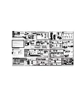
1) Disconnect the two FFCs.
2) Remove four screws [C] from the rear panel.
3) Remove four screws [F] on the P.C.B.
4) Release the stopper.
5) Lift the entire VCR P.C.B, and then remove it in the direction of the arrow.
Caution when reinstalling VCR P.C.B:
Position the VCR P.C.B according to the positioning boss.
Fig. 4-2-9 VCR P.C.B
(6) TIMER P.C.B
1) Remove the front holder.
2) Unplug the direct connectors from the VCR P.C.B.
3) Unplug the connector.
Information
Release the four stoppers of front holder: The TIMER P.C.B can be detached without removing the
deck mechanism.
Fig. 4-2-8 TIMER P.C.B
Disassembly and Reassembly > Cabinet Disassembly
[C] M3X8 [Black] [F] M3X6.5 [Gold]
3) Screw [F]
2) Screw [C]
2) Screw [C]
3) Screw [F]
3) Screw [F]
1) FFC Connector
3) Screw [F]
Positioning boss
4) Stopper
5)
VCR P.C.B
*FFC: Flexible flat cable
1) Front Holder
2) Direct Connector
Stopper
TIMER P.C.B
3) Connector
Summary of Contents for DV-RV8500E
Page 70: ...THE UPDATED PARTS LIST FOR THIS MODEL IS AVAILABLE ON ESTA ...
Page 82: ...LOCATION GUIDE C 1 C Circuit Board Diagrams C 1 VCR Circuit Board Diagram COMPONENT SIDE ...
Page 83: ...LOCATION GUIDE C 2 CONDUCTOR SIDE ...
Page 84: ...LOCATION GUIDE CONDUCTOR SIDE C 3 C 2 S M P S Circuit Board Diagram ...


