31
ED-X10/ED-X12(CC9XM2)
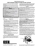
7. Wiring diagram
Wiring diagram 1
CN102
CN103
CN101
CNP
O
W
CN
PWR
TSW
FB2
FB2
50
±5
mm
CNP
W
R
FB5
Z2
Wiring of the circuit power supply (1/2)
Wiring of the circuit power supply main board
(1)Connect the
TSW
. Make sure to confirm the seal (based
on the diagram below) when attaching the
TSW
.
(2)Connect the CNPWR, attach FB2
(3)Connect the CNPOW
, attach FB5
Make sure to securely connect the CNPOW
,
TSW
, and
CNPWR to the circuit power supply (as it cannot be confirmed
whether they are securely connected in later processes).
The operations with this symbol have implications with
laws/standards. It is possible to be in violation of these
laws/standards in the case that these operations are not
carried out according to the instructions.
Assemble
according to the operation instructions.
Area of Importance
Area of Importance
Heat sink
Heat sink
Attach the FB2 (ferrite core) to the CNPWR.
Make sure to completely lock the hook when attaching the FB2.
Secure the FB2 to the CNPWR with the cable tie Z2, as
indicated in the diagram.
Cut the cable tie with 2 to 3 mm of excess length remaining.
Make sure to confirm the print of the
TSW
.
Seal
Area of Importance
Confirm that the print indicates
Attach the FB5 (ferrite core) to CNPOW
.
Make sure to completely lock the hook
when attaching the FB5.
Area of Importance
It is not necessary to secure the FB5
with a cable tie.