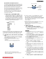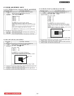
NOTE: (1) If there is a different value than shown in I2C Parameter List, for
fixed data, adjust it using
,
buttons (only in this case
)
* JIG. R/C FACTORY PRESET CODE:92
MEMORY INITIALIZE and FACTORY PRESET
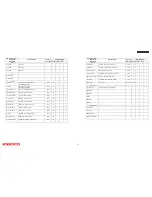
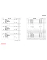
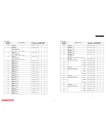
ITEM MEMORY
INITIALIZE
FACTORY RESET
REMARKS
H POSITION ADJUST DATA
INITIALIZE
NOT INITIALIZE
V POSITION ADJUST DATA
INITIALIZE
NOT INITIALIZE
RGB(480p) ADJUST DATA
INITIALIZE
NOT INITIALIZE
SETTING DATA FOR EACH DEVICE
INITIALIZE
NOT INITIALIZE
BBE EFFECT SETTING DATA
INITIALIZE
NOT INITIALIZE
AUDIO AGC SETTING DATA
INITIALIZE
NOT INITIALIZE
V CHIP RATING SETTING DATA
INITIALIZE
NOT INITIALIZE
CCD SETTING DATA INITIALIZE NOT INITIALIZE
FACTORY RESET ITEM
INITIALIZE
INITIALIZE
LAMP TIME
INITIALIZE
INITIALIZE
Accumulate TIME
INITIALIZE
NOT INITIALIZE
GHOST ADJUST DATA
INITIALIZE
NOT INITIALIZE
FLICKER ADJUST DATA(V.COM)
INITIALIZE
NOT INITIALIZE
NRSH ADJUST DATA
INITIALIZE
NOT INITIALIZE
COLOR UNIFORMITY
NOT INITIALIZE
NOT INITIALIZE
GAMMA CORRECTION
NOT INITIALIZE
NOT INITIALIZE
V.REF (EPSON PANEL ONLY )
NOT INITIALIZE
NOT INITIALIZE
Automatic Power saving- Yes/No
Set to “No”
for heat-run
Set to Yes
(
8
)
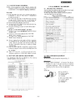
When PTV turns ON , it will tune CH03 this is the
complete
operation
of
FACTORY RESET
process.
·Process of FACTORY RESET operation.
A screen is be colored
MAGENTA
when
FACTORY
RESET
start.
A screen is be colored
green
when
FACTORY
RESET
finish normally.
A screen is be colored
black
when
FACTORY
RESET
finish abnormally.
(6) Do not unplug from AC outlet until this operation
is complete and do not perform any key operation
either, after this operation each factory setting and
all adjust mode data should reset to delivery settings
automatically.
(7)
After
FACTORY
RESET
, it should be unplug AC cord.
Unplug and plug AC cord and then all settings and data
①
②
③
are updated.
1-3
FACTORY RESET
OPERATION
NOTE: The execution of this function returns the
adjustment
made by the customer , this will return all the
adjustments to the
original shipping conditions.
Procedure
(1) Enter Adjustment mode by the method described in
sub-items 1.1 and 1.2 from item 1 (“Adjustment
procedure start up”).
(2) Get to the second page of Adjust Mode by pressing
remote control “Menu” key once, or with either the
R/C or front panel
G
,
H
cursor keys several times.
(3) Select
FACTORY RESET
adjust code.
(4)
Activate
FACTORY RESET
by pressing
E
cursor key
for
more than 3 seconds.
(5) Check the
following process for FACTORY RESET
operation.
1-4
FACTORY AND SERVICE ADJUSTMENTS
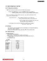
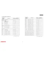
The adjustment item that is affected by the memory
initialize operation is shown below:
II Final ASSEMBLY ADJUSTMENT
2 - 1
PRE HEAT RUN CONDITION
Heat run should be performed with moving picture or no signal.
And disable side panel or
top/bottom panel.
Do NOT use stock market quotation, computer graphics,
and other fixed (non-moving) image.
Table 2
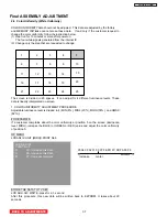
.1 Final adjustment order
Order Adjustment
Item
Signal
1
SUB CONTRAST
ADJUSTMENT
(RGB) White Raster 480i,720P
2 RASTER POSITION ADJUSTMENT Circle pattern signal.
3 GHOST
ADJUSTMENT
4 FLICKER
ADJUSTMENT
5 NRSH
ADJUSTMENT
6 White Balance (GAMMA) ADJUSTMENT
7 WHITE UNIFORMITY ADJUSTMENT
8 DOT STRIPE CHECKING and ADJUSTMENT
9 SUB GHOST CHECKING and ADJUSTMENT
10 HORIZONTAL CROSS TALK CHECKING
and ADJUSTMENT
11 LAMP DOOR PROTECTION OPERATION
CHECK
12
LAMP HOLDER PROTECTION OPERATION CHECK
13
HIGH TEMPERATURE PROTECTION
OPERATION CHECK
14 TEMPERATURE SENSOR OPERATION CH
E
CK
15
HDMI ADJUSTMENT / EDID DATA
INSTALLATION
16
17
18
19
20
2-2
SUB-CONTRAST ADJUSTMENT
Preparation
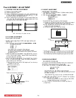
Receive Sub-contrast adjustment signal (Fig. 1).
Adjustment
(1) Select ‘SUB CONTRAST’ of Service Adj. Menu.
Press
E
for over 2 seconds and have it perform
automatic adjustment. When it’s completed, ‘Auto
Adjusting’ on the screen will be disappeared.
V
1
V
3
V
2
Fig. 1
Full White
(RF Input ANT A))
V
1
=1.0 Vp-p (when
V
2
=100IRE with
V
3
=7.51IRE)
(
Y P
B
P
R
Input
720p,1080i
)
V
1
=1.0 Vp-p (when
V
2
=100IRE with
V
3
=7.51IRE)
LC58/LC58E
BACK TO ADJUSTMENTS
33
Summary of Contents for 50VF820 - 50" Rear Projection TV
Page 96: ...LC58 LC58E CIRCUIT BLOCK DIAGRAM TABLE OF CONTENTS 96 ...
Page 97: ...LC58 LC58E POWER SUPPLY BLOCK DIAGRAM TABLE OF CONTENTS 97 ...
Page 98: ...CONNECTION DIAGRAM TABLE OF CONTENTS LC58 LC58E 98 ...
Page 105: ...LC58 chassis Model 50VF820 55VF820 60VF820 1 FRONT PANEL 2 REAR PANEL LC58 LC58E 105 ...
Page 106: ...LC58E chassis Model 50VG825 55VG825 60VG825 1 FRONT PANEL 2 REAR PANEL LC58 LC58E 106 ...
Page 155: ...SIGNAL PWB Solder side PRINTED CIRCUIT BOARDS BACK TO TABLE OF CONTENTS LC58 LC58E 155 ...
Page 159: ...PRINTED CIRCUIT BOARDS POWER PWB Solder side BACK TO TABLE OF CONTENTS LC58 LC58E 159 ...
Page 190: ......


