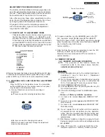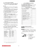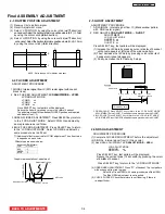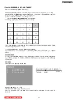
Final ASSEMBLY ADJUSTMENT
2-
1
1
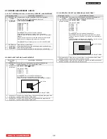
LAMP DOOR PROTECTION OPERATION CHECK
Adjustment procedure
(1) Remove Lamp cover and turn the set on.
(2) Check that the lamp dose not light and “Lamp indicator” flash red.
(3) Turn the set off and attach Lamp cover again
2-
1
2
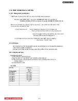
LAMP HOLDER PROTECTION OPERATION CHECK
Adjustment procedure
(1) Remove Lamp holder and turn the set on. (attach Lamp cover)
(2) Check that the lamp dose not light and “Lamp indicator” flash red.
(3) Turn the set off and attach Lamp holder again
2-
1
3
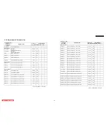
HIGH TEMPERATURE PROTECTION OPERATION CHECK
Adjustment procedure
(1) Remove EPF2 connector while the set is on.
(2) Check that the lamp is turned off and “Temp indicator” flash red.
(3) Turn the set off and attach EPF2 again.
(4) Remove EPF3 connector while the set is on.
(5) Check that the lamp is turned off and “Temp indicator” flash red.
(6) Turn the set off and attach EPF3 again.
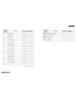
(7) Turn the set on and remove the connector of temperature sensor terminals on optical
engine.
(8) Check that the lamp is turned off and “Temp indicator” lights in red.
LC58/LC58E
BACK TO ADJUSTMENTS
39
Summary of Contents for 50VF820 - 50" Rear Projection TV
Page 96: ...LC58 LC58E CIRCUIT BLOCK DIAGRAM TABLE OF CONTENTS 96 ...
Page 97: ...LC58 LC58E POWER SUPPLY BLOCK DIAGRAM TABLE OF CONTENTS 97 ...
Page 98: ...CONNECTION DIAGRAM TABLE OF CONTENTS LC58 LC58E 98 ...
Page 105: ...LC58 chassis Model 50VF820 55VF820 60VF820 1 FRONT PANEL 2 REAR PANEL LC58 LC58E 105 ...
Page 106: ...LC58E chassis Model 50VG825 55VG825 60VG825 1 FRONT PANEL 2 REAR PANEL LC58 LC58E 106 ...
Page 155: ...SIGNAL PWB Solder side PRINTED CIRCUIT BOARDS BACK TO TABLE OF CONTENTS LC58 LC58E 155 ...
Page 159: ...PRINTED CIRCUIT BOARDS POWER PWB Solder side BACK TO TABLE OF CONTENTS LC58 LC58E 159 ...
Page 190: ......


