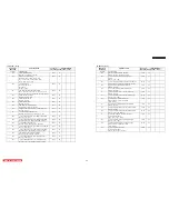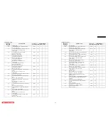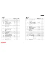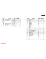
HDMI (2/2)
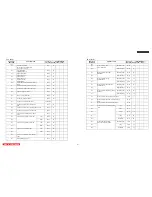
Initial Data(HEX)
Adjustment
Mode OSD
Adjustment Item
Adjustment
Range(HEX)
LC58E LC58 LC57
HDMI HDMI_1/2
023
SPD info frame type code
00~FF
*
←
←
←
024
SPD info frame version code
00~FF
*
←
←
←
025
SPD info frame data
00~FF
*
←
←
←
026
AUDIO Info Frame Type Code 1
00~FF
*
←
←
←
027
AUDIO Info Frame Version Code 1
00~FF
*
←
←
←
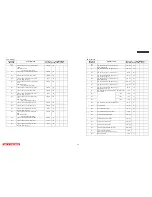
028
00~FF
*
←
←
←
029
00~FF
*
←
←
←
030
00~FF
*
←
←
←
031
00~FF
*
←
←
←
032
AUDIO Info Frame Data Bytes 1
00~FF
*
←
←
←
033 GCP
data
00~FF
*
←
←
←
034
ACP packet type code
00~FF
*
←
←
←
035 ACP
type
00~FF
*
←
←
←
036
DVD-audio type dependent generation
00~FF
*
←
←
←
037
Audio copy information
00~FF
*
←
←
←
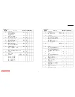
038
RGB to YCbCr range scaling
00~01
01
←
←
←
039
Back Porch Mode, Field 2 Position Adjustment
00~01
01
←
←
←
040
Matching Test to allow increment of stability counter.
00~01
00
←
←
←
041
RGB to YCbCr range scaling
00~01
01
←
←
←
042
Back Porch Mode, Field 2 Position Adjustment
00~01
01
←
←
←
043
Matching Test to allow increment of stability counter.
00~01
00
←
←
←
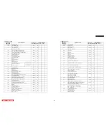
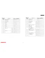
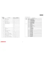
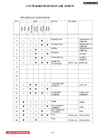
ISF Adjutment Mode List
ISF Adjustment Mode
Device OSD
Item
H_POSITION
Horizontal Position Adjustment
1st Page
V_POSITION
Vertical Position Adjustment
001
LCD DRIVE R-SUB GAIN (High)
002
LCD DRIVE G-SUB GAIN (High)
003
LCD DRIVE B-SUB GAIN (High)
004
LCD DRIVE R-SUB GAIN (Medium)
005
LCD DRIVE G-SUB GAIN (Medium)
006
LCD DRIVE B-SUB GAIN (Medium)
007
LCD DRIVE R-SUB GAIN (STD)
008
LCD DRIVE G-SUB GAIN (STD)
009
LCD DRIVE B-SUB GAIN (STD)
010
LCD DRIVE R-SUB GAIN (B/W)
011
LCD DRIVE G-SUB GAIN (B/W)
Drive Micro
012
LCD DRIVE B-SUB GAIN (B/W)
001 Black
Stretch
002 Black
Correction
003 Histogram
Gamma
004 Histogram
Enhancer
005 Histogram
Amp
006
Histogram Color Management
007
Dynamic Backlight/Lamp Correction
008 Dynamic
Shading
009
Bgm Gain OFF
016 Contrast
Center
017
Red Gain Adjustment
Color Temperature: High
018
Green Gain Adjustment
Color Temperature: High
019
Blue Gain Adjustment
Color Temperature: High
020
Red Line 1 Setting
021
Red Line 2 Setting
022
Red Line 3 Setting
023
Red Line 4 Setting
024
Red Line 5 Setting
025
Red Line 6 Setting
026
Red Line 8 Setting
027
Red Line 10 Setting
028
Red Line 12 Setting
029
Red Line 14 Setting
030
Blue Line 1 Setting
031
Blue Line 2 Setting
032
Blue Line 3 Setting
033
Blue Line 4 Setting
034
Blue Line 5 Setting
035
Blue Line 6 Setting
036
Blue Line 8 Setting
037
Blue Line 10 Setting
038
Blue Line 12 Setting
039
Blue Line 14 Setting
FC6
040
RGB Output Mode
LC58/LC58E
BACK TO ADJUSTMENTS
75
Summary of Contents for 50VF820 - 50" Rear Projection TV
Page 96: ...LC58 LC58E CIRCUIT BLOCK DIAGRAM TABLE OF CONTENTS 96 ...
Page 97: ...LC58 LC58E POWER SUPPLY BLOCK DIAGRAM TABLE OF CONTENTS 97 ...
Page 98: ...CONNECTION DIAGRAM TABLE OF CONTENTS LC58 LC58E 98 ...
Page 105: ...LC58 chassis Model 50VF820 55VF820 60VF820 1 FRONT PANEL 2 REAR PANEL LC58 LC58E 105 ...
Page 106: ...LC58E chassis Model 50VG825 55VG825 60VG825 1 FRONT PANEL 2 REAR PANEL LC58 LC58E 106 ...
Page 155: ...SIGNAL PWB Solder side PRINTED CIRCUIT BOARDS BACK TO TABLE OF CONTENTS LC58 LC58E 155 ...
Page 159: ...PRINTED CIRCUIT BOARDS POWER PWB Solder side BACK TO TABLE OF CONTENTS LC58 LC58E 159 ...
Page 190: ......

