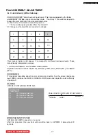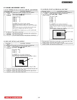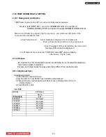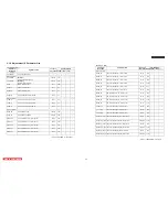
2.10 DRIVE ADJUSTMENT CHECK
2
.
10
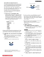
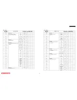
.1 DOT STRIPE(vertical lines 12 dot width) CHECKING and ADJUSTMENT
ADJUSTMENT ITEMS
ADJUSTMENT PROCEDURE
0
PREPARATION Complete White uniformity adjustment before the adjustment.
1
SIGNAL
Internal signal from IC
(
Dot pattern with gray scale
)
2
RED Stripe
adjustment
LCD ADJUST MODE
→
STRIPE
LCD ADJUST MODE
STRIPE R0 xx
STRIPE R1 xx
STRIPE R2 xx
STRIPE R3 xx
STRIPE R4 xx
Press SELECT key, test pattern will be displayed.
Check that no vertical line with pitch of 12 dots on screen.
If there is, adjust the data by pressing left or right cursor stick
◄►
of
handset.
5 signal levels are required to check and adjust the vertical stripes.
Signal levels are changed pressing
▼
cursor of handset.
Press SELECT key of handset return to the LCD ADJUST MODE.
3
GREEN Stripe
adjustment
Press “
▼
” key to select Green.
Check and adjust Green stripe with same procedure as Red Stripe.
4
BLUE Stripe
adjustment
Press “
▼
” key to select Blue.
Check and adjust Blue stripe with same procedure as Red Stripe.
2
.
10
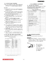
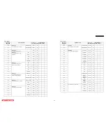
.2 SUB GHOST CHECKING and ADJUSTMENT
ADJUSTMENT
ITEMS
ADJUSTMENT PROCEDURE
0 PREPARATION
Complete White uniformity adjustment before the adjustment.
1 SIGNAL Internal signal from IC
(
50% white window pattern
)
2 Sub Ghost R
adjustment
LCD ADJUST MODE
→
S GHOST
LCD ADJUST MODE
S GHOST R xxx
S GHOST G xxx
S GHOST B xxx
Press SELECT key, test pattern will be displayed
Check that no ghost on right hand side of the window.
If there is, decrease Ghost by pressing cursor stick
◄►
of handset
Press SELECT key of handset return to the LCD ADJUST MODE.
3
Sub Ghost G
adjustment
Press “
▼
” key to select green. Check and adjust sub ghost green with
same procedure as Red SUB GHOST.
4 Sub Ghost B
adjustment
Press “
▼
” key to select blue. Check and adjust sub ghost blue with
same procedure as Red SUB GHOST.
SUB GHOST
12dots
2
.
10
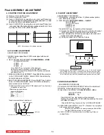
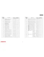
.3 HORIZONTAL CROSS TALK CHECKING and ADJUSTMENT
ADJUSTMENT ITEMS ADJUSTMENT PROCEDURE
0 PREPARATION
Complete White uniformity adjustment before the adjustment.
1 SIGNAL
Internal signal from IC (50% white window pattern)
2 STREAK
LEVEL
R
STREAK SLOPE R
LCD ADJUST MODE
→
STREAK
LCD ADJUST MODE
R LEVEL xx
R SLOPE xx
G LEVEL xx
G SLOPE xx
B LEVEL xx
B SLOPE xx
Press SELECT key, test pattern will be displayed
Check that no horizontal cross talk on right side of the window.
If there is, adjust the ”R-LEVEL” by pressing cursor stick
◄►
of
handset.
If cross talk does not disappear with “R-LEVEL”, press
▼
key and
adjust “R-SLOPE” until cross talk is disappeared.
Press SELECT key of handset return to the LCD ADJUST MODE.
3 STREAK LEVEL G
STREAK SLOPE G
Press “
▼
” key to select Green. Check and adjust Green Streak
with same procedure as Red cross talk.
4 STREAK LEVEL B
STREAK SLOPE B
Press “
▼
” key to select Blue. Check and adjust Blue Streak with
same procedure as Red cross talk.
Horizontal Crosstalk
LC58/LC58E
BACK TO ADJUSTMENTS
38
Summary of Contents for 50VF820 - 50" Rear Projection TV
Page 96: ...LC58 LC58E CIRCUIT BLOCK DIAGRAM TABLE OF CONTENTS 96 ...
Page 97: ...LC58 LC58E POWER SUPPLY BLOCK DIAGRAM TABLE OF CONTENTS 97 ...
Page 98: ...CONNECTION DIAGRAM TABLE OF CONTENTS LC58 LC58E 98 ...
Page 105: ...LC58 chassis Model 50VF820 55VF820 60VF820 1 FRONT PANEL 2 REAR PANEL LC58 LC58E 105 ...
Page 106: ...LC58E chassis Model 50VG825 55VG825 60VG825 1 FRONT PANEL 2 REAR PANEL LC58 LC58E 106 ...
Page 155: ...SIGNAL PWB Solder side PRINTED CIRCUIT BOARDS BACK TO TABLE OF CONTENTS LC58 LC58E 155 ...
Page 159: ...PRINTED CIRCUIT BOARDS POWER PWB Solder side BACK TO TABLE OF CONTENTS LC58 LC58E 159 ...
Page 190: ......

