


3.3 Connecting the Unit to a PC
16
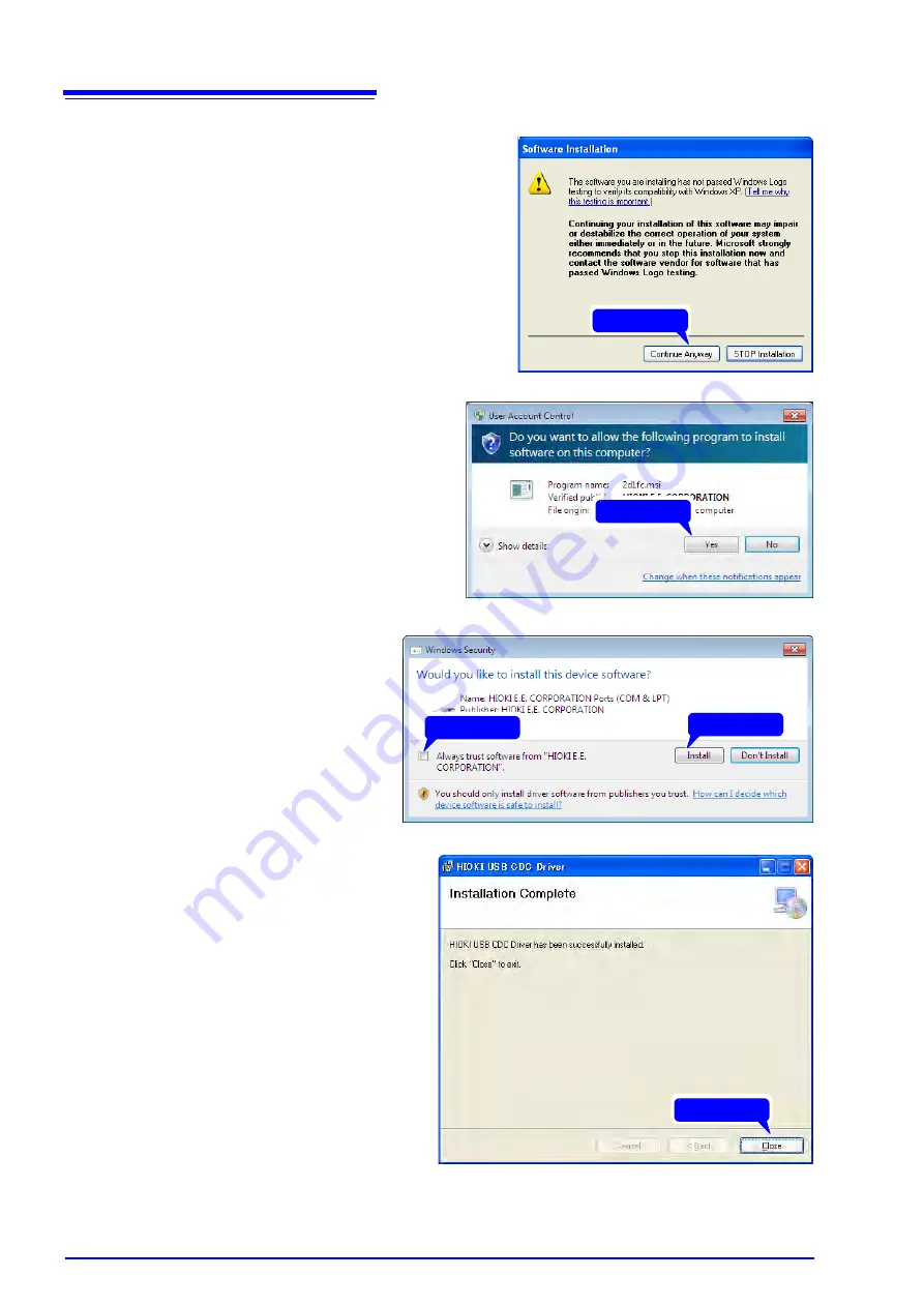
For Windows XP
During the installation, a message saying
that the software has not passed Windows
Logo testing will appear a few times, click
[Continue Anyway]
to continue installing.
For Windows Vista/7/8
When a dialog box requesting your per-
mission to continue the program appears,
click
[Yes]
.
Sometimes another dialog box requesting
your permission to install the software may
appear. When it does, check
[Always
trust software from "HIOKI E.E. COR-
PORATION"]
and click
[Install]
to contin-
ue.
5
When installation is completed
and the dialog box appears,
click
[Close]
to exit.
This completes the driver installation.
Click
Click
1 Check
2 Click
Click
Summary of Contents for MR8904
Page 1: ...MR8904 Instruction Manual CAN UNIT EN Sept 2018 Revised edition 3 MR8904A981 03 18 09H...
Page 2: ......
Page 10: ...Usage Notes 6...
Page 14: ...10...
Page 24: ...3 3 Connecting the Unit to a PC 20...
Page 66: ...7 4 MR8904 CAN Editor General Specifications 62...
Page 69: ......
Page 70: ......
Page 71: ......
Page 72: ......


