

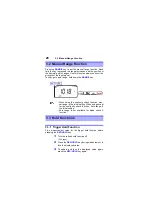


2.6 Diode Check
24
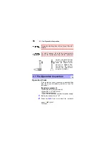
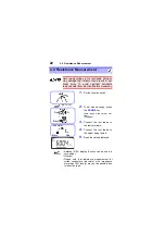
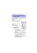
2.6 Diode Check
Never apply voltage to the test leads. Doing
so may damage the instrument and result in
personal injury. To avoid electrical accidents,
remove power from the circuit before mea-
suring.
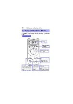
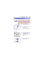
1.
Set the function switch.
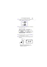
2.
Connect the test leads to
the test terminals.
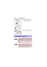
3.
Connect the test leads to
the object being tested.
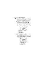
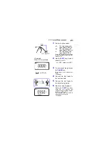
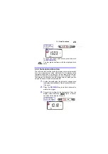
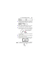
4.
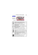
Read the value displayed.
With a normal diode, the
sequential order voltage (0.3 to
0.8 V) is displayed.
When the display value less
than 0.050 V, buzzer sounds.
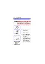
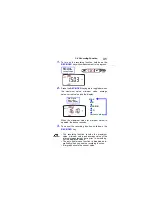
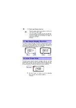
When the display value drops to
the range of 0.3 to 0.8 V, a sin-
gle buzzer sounds to indicate
that a diode was detected.
However, in relative value dis-
play mode, this conforms with
the internally measured value,
not the display value.
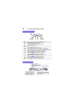
<Example>
Red
Black
Cathode
Anode
Sequen-
tial order
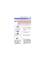
Red
Black
Summary of Contents for 3804-50
Page 2: ......
Page 12: ...ご使用にあたっての注意 8 ...
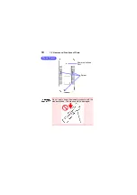
Page 18: ...1 2 各部の名称と機能 14 スタンドを立てたまま 上方向から強い力を加えないでくださ い スタンドを損傷します ネジ 通信ポート 背面 ...
Page 30: ...2 7 コンデンサ容量測定 26 ...
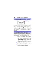
Page 42: ...3 11 通信機能 オプション 38 コネクタを本器から外す場合はツメを押しながら引き 抜きます ツメ ...
Page 54: ...5 3 確度 50 ...
Page 60: ...6 5 全点灯表示の確認方法 56 ...
Page 64: ......
Page 66: ......
Page 76: ...8 ...
Page 94: ...2 7 Capacitance Measurement 26 ...
Page 106: ...3 11 Communications Function 38 ...
Page 125: ...索引 4 3 2 1 7 6 5 10 9 8 ...
Page 126: ......
Page 129: ......