ID7000 Series Smart Code Reader User Manual
43
used as
device’s
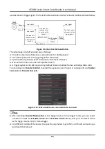
trigger signal. The function demonstration of shaft encoder module is shown below.
Phase A
Phase B
Line Input 1
Line Input 2
Line input 1 is
selected as the
input signal for
phase A
Line input 2 is
selected as the
input signal for
phase B
Phase A Input
Phase B Input
Shaft Encoder
Software
Module
Line Trigger
Module
Output
The final output
of module is line
trigger s ignal
Figure 9-14 Function Demonstration
The advantages of shaft encoder are as follows:
●
Encoder output pulse frequency is proportional to rotating speed.
●
The output pulse acts as a trigger signal for the device.
●
Synchronize acquisition speed and sample movement of device.
●
Non-uniform motion can also be a perfect match.
●
A trigger signal can be set as acquiring multiple lines or multiple frames with adjustable ratio.
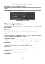
You should go to
Encoder Control
to select the signal source of signal A and signal B via
Encoder
Source A
and
Encoder Source B
.
Figure 9-15 Set Encoder Source A and Encoder Source B
Note
●
After selecting
Encoder Module Out
as the trigger source in line trigger mode, you can select
LineIn0 or LineIn1 for
Encoder Source A
and
Encoder Source B
only. And you can select LineIn2
as the trigger source only in frame trigger.
●
For different models of the device, the specific parameters may differ, and the actual device you
purchased shall prevail.

