ID7000 Series Smart Code Reader User Manual
4
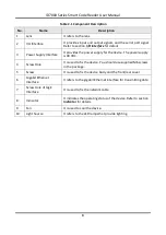
Table 2-1 Component Description
No.
Name
Description
1
Lens
It refers to the lens.
2
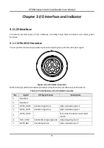
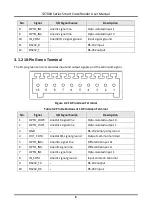
I/O Interface
It provides input and output signals, and the serial port signal.
Refer to section
3
Power Supply Interface
It provides the power supply for the device. The power supply
is 48 VDC.
4
Screw Hole
It is used to fix the device. You should use supplied M6 screws
in the package.
5
Screw
It is used to fix the device body and the front/rear cover.
6
Gigabit Ethernet
Interface
It refers to the gigabit Ethernet interface for transmitting data.
7
Screw Hole of GigE
Interface
It is used to fix the network cable.
8
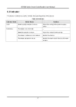
Indicator
It indicates the operating status of the device. Refer to section
for details.
9
Fan
It is used to cool the device.
10
Light Source
It refers to the LED lamps that provide lighting.


