CameraLink Line Scan Camera
·
User Manual
38
RO
RO
RO
RO
R4
R3
R1
R2
D
RT
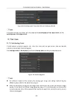
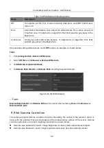
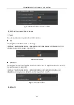
Figure 8-2
RS-422 Bus Topology with 4 Receivers
When the camera is the last receiver on the bus structure, the camera's terminal resistance needs
to be enabled, and the rest camera's terminal resistance need to be disabled. Multiple terminal
resistance should not be enabled on the bus structure, which will reduce signal reliability and may
cause damage to the RS-422 device.
RS-644 Standard Input
If the camera’s input terminal adopts RS-644 standard signal, the input terminal must enable 120 Ω
terminal resistance.
LVTTL Standard Input
If the camera’s input terminal adopts LVTTL standard signal, the input terminal’s 120 Ω terminal
resistance must be disabled, and its input electrical feature requirement is shown below.
Table 8-1
Electrical Feature Requirement of LVTTL
Voltage
Description
+0 V to +5.0 V
It is a recommended working voltage.
+0 V to + 0.8 V
The voltage stands for logic 0.
0.8 V to +2.0 V
It is an area where transformation occurs.
There is no logic status in this area.
> +2.0 V
The voltage stands for logic 1.
+6.0 V
The max. voltage value. If exceeding this value,
the camera may be damaged.

