


DTS-60A / DTS-100A O
PERATORS
M
ANUAL
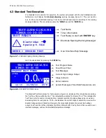
5.1.2 Test Operations
Every Test operates according to the programmable parameters of the above sessions. This section
will describe the operations of the system in respect with the programmable parameters.
During Startup the system initializes the
Startup Wait Timer - SWT
and the
Startup Stirrer Timer
- SST
. The system introduces an idle operation time according the 1
st
timer, which is used as a ‘Wait
time after filling period’. During this time the system could turn on the stirrer according the 2
nd
Timer.
If the 2
nd
Timer is zero the stirrer is disabled.
The Test continues the operation according to the parameters described in the 1
st
Stage. The
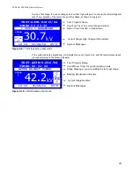
Voltage
Parameter and the
Duration
are inputs to the voltage controller, which will control the high voltage
output. More specifically, if the voltage value indicates kV then the voltage controller will immediately
adjust (according to the maximum system’s rate) the output voltage to the programmed value
therefore keeping the voltage stable for the specified Duration Parameter. If the voltage value
indicates kV/sec then the voltage controller will adjust the output voltage according to the desired rate
for the specified duration. It is noted that the Duration Parameter could take the value “Breakdown”
which means no specified duration.
During both situations, if a breakdown is detected the output voltage is immediately disconnected
(turned-off) and the Test Program proceeds with the
After Breakdown Wait Timer - ABDWT
and
the
After Breakdown Stirrer Timer - ABDST
. During the 1
st
of these timers the system will be idle,
concerning the output voltage. Moreover, the stirrer will be enabled for a duration according to the 2
nd
timer.
The Test Program will proceed to the stage indicated by the
After Breakdown Stage
–
ABDSTG
parameter (0-29). There are the following exceptions:
i. Indication of a stage prior to the current stage leads to program termination
ii. Indication of a stage next (30) leads to next stage
iii. Indication of a stage end (31) leads to program termination
It is noted that after every breakdown the output voltage will be initialized, thus the next stage’s
start voltage will be zero (0 kV). If a breakdown isn’t detected, the program proceeds to the next
stage bypassing the After Breakdown Wait Timer, the After Breakdown Stirrer Timer and the After
Breakdown Stage.
The test termination will prompt the user to print a test results receipt and finally displays a
Results screen.
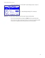
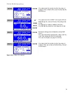
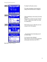
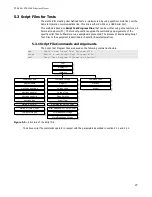
The above operations are illustrated in Figure 5-1.
45
Summary of Contents for DTS-100A
Page 92: ......


