


DTS-60A / DTS-100A O
PERATORS
M
ANUAL
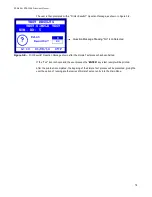
4.3 Standard Test Execution
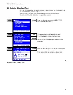
If a standard test is selected for execution, the system will proceed with the test initialisations and
furthermore it will display the
Electrode Spacing
warning message, Figure 4-7. The user must be
sure for the current Electrode Spacing; if not he must check and adjust it according to the warning
message indication. The only active keys are the
‘MENU’
key and the
‘ENTER’
key.
Figure 4-7 –
Electrode Spacing Warning Message
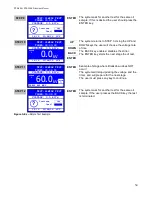
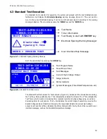
Start the selected test by pressing the
‘ENTER’
key
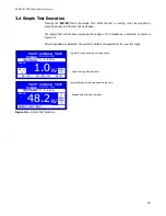
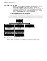
Figure 4-8 –
Standard Test Main Screen
The Standard Test Main Screen for Test execution, Figure 4-8, includes all the information concerning
the Test flow. More specifically, the 1
st
line indicates the selected Test Name. The 2
nd
line indicates the
Test Timer, which is used as increasing timer (seconds resolution) during voltage rising, as well as a
decreasing timer for wait periods. The 3
rd
line indicates the current Stage of execution, as well as the
desired Voltage value and Duration. Obviously, the large digits indicate the current high voltage
output (in kV) and the left icon indicates the Stirrer State (on/off). Finally, the last line is used for user
interface messages, such as the time/date/temperature message.
39
Test Name
Timer Information
Test Ready to start with
'ENTER'
key
Electrode Spacing Warning Message!
User Interface Help Message
TEST:ASTM-D1816/84
TIMER:00:00:00
TEST READY...
ENTER > PROCEED TEST
Electrodes:
Spacing:0.04in
STARTUP WAIT TIMER...
0.0
Test Program Name
Count Down Timer
Test Messages
Current High Voltage Output
Stirrer Indicator
System Messages (Time/Date/Temperature. etc)
kV
STIR
STAGE
1
Stage Indicator
TEST:ASTM-D1816/84
TIMER:00:00:00
12:10 01/08/16 65°F
Summary of Contents for DTS-100A
Page 92: ......


