


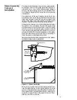

5
!
!
1
Preliminaries
About Your Warranty
Failure to follow all of these instructions will void your Warranty and may
present a fire hazard.
Therefore, please be sure to read and carefully follow all
of the instructions contained in this guide. Any component that is found to be
faulty
must be
replaced with an approved component. Tampering with the
fireplace components is DANGEROUS and voids all warranties.
The Heat-N-Glo Warranty will be voided by, and Heat-N-Glo disclaims any
responsibility for, the following actions:
Installation of any damaged fireplace or vent system component.
Modification of the fireplace or direct vent system.
Installation other than as instructed by Heat-N-Glo.
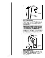
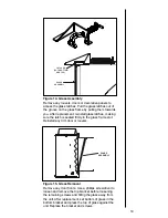
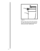
Improper positioning of the gas logs or the glass door.
Installation and/or use of any component part not manufactured and approved
by Heat-N-Glo, not withstanding any independent testing laboratory or other
party approval of such component part or accessory.
Approval Listings and Codes
Appliance Certification
The Heat-N-Glo gas fireplaces discussed in this
Owners Guide
have been tested to
certification standards and listed by the applicable laboratories. See the
Installers
Guide
and Rating Plate for your fireplace.
Installation Codes
The installation must conform with local codes or, in the absence of local codes,
with the National Fuel Gas Code ANSI Z223.1 (in the United States) or CAN/CGA-
B149 Installation Codes (in Canada). The appliance, when installed, must be
electrically grounded in accordance with local codes or, in the absence of local
codes with the National Electric Code ANSI/NFPA 70 (in the United States) or the
Canadian Electric Code CSA C22.1(in Canada).
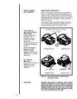
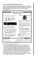
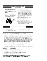
The Gas Control Systems
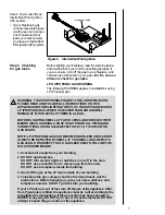
WARNING: THIS UNIT IS NOT FOR USE WITH SOLID FUEL.
Three types of gas control systems are used with these models: Standing Pilot
Ignition, Direct Spark Ignition and Intermittent Pilot Ignition.
Standing Pilot Ignition System
This system includes millivolt control valve, standing pilot, thermopile/thermo-
couple flame sensor, and piezo ignitor.
WARNING: 110-120 VAC MUST NEVER BE CONNECTED TO A
CONTROL VALVE IN A MILLIVOLT SYSTEM.
Direct Spark Ignition (DSI) System
This system includes a 110V control valve, electronic module and spark ignitor/
flame sensor.
Intermittent Pilot Ignition (IPI) System
This system includes a 3V transformer, 3V electronic module, 3V control valve,
intermittent sparking pilot, and battery back-up.
WARNING: CONTINUOUS 110-120 VAC SERVICE MUST BE WIRED
DIRECTLY TO THE FIREPLACE JUNCTION BOX IN AN IPI OR DSI
SYSTEM.
!