


25
07/22
7027-804H
E. Panel and Trim Set
Standard Size: 30 inches H x 40 inches W
(762mm x 1016mm)
Large Size: 33 inches H x 50 inches W
(838mm x 1270mm)
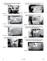
1.
Unpack and lay out parts face down (flanges up) on a
non-abrasive surface.
2. Install (1) 8-32 x 3/8 inch screw into bottom tab of side
panel
Figure 25.1
.
3. Set the large hole at bottom of side curtain over screw
installed in
Figure 25.2
.
4. Stand assembly on end and attach and install (1) 8-32
x 3/8 inch screw through tab in side panel and curtain
(Figure 25.3)
.
5. Align top panel to side panel setting clearance hole
over screw head in side panel/curtain assembly. Install
(2) 8-32 x 3/8 inch screws through holes in side panel
into top panel
(Figure 25.4)
. Complete for both sides.
Figure 25.1
NOTE:
*Right and left side curtains are shipped with
the insert.
Figure 25.2
Figure 25.3
Figure 25.4
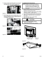
6. Hold side curtains in open position and lower panel
set over insert setting lower edge of top panel in slot
between hopper lid and panel support as shown in
Figure 25.5
. Place existing screw head into locater
hole in floor of insert
(Figure 25.6.)
7. Lift hopper lid and press down on panel top while
installing (4) 8-32 x 3/8 inch screws into holes in panel
support. (If screws have been factory installed, tighten
to secure panel to panel support.) Return hopper lid to
closed position
(Figure 25.7)
.
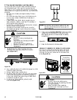
8. Install a corner bracket on each side trim piece. Slide
brackets into top trim from each side and secure
with flathead screwdriver
(Figure 25.8)
. Attach trim
assembly to panel set as follows:
a. Ensure that brackets face towards the back.
b. Align trim assembly to panel set sides and
slide down.
Figure 25.7
Figure 25.8
Panel Locator Hole
Figure 25.5
Figure 25.6
Summary of Contents for Quadra-Fire CB1200
Page 31: ...31 07 22 7027 804H...


