Abmessungen
58
A4429-3.0
HBM: public
T40FH
20°
18x20°=360°
Ø470
0,5°
Min. Biegeradius
R=20
Ø37
75,5°
Ø18
Ausbruch im
Schnitt B-B
Abmessungen in mmMaße ohne Toleranzangabennach DIN ISO 2768-mk
Page 1: ...Mounting Instructions Montageanleitung English Deutsch T40FH...
Page 2: ...3 0 HBM public 09 2017 E Hottinger Baldwin Messtechnik GmbH Subject to modifications All product descriptions are for general information only They are not to be understood as a guarantee of quality o...
Page 3: ...Mounting Instructions Montageanleitung English Deutsch T40FH...
Page 4: ...he rotor mounting 19 5 6 Mounting the rotor 22 5 7 Installing the stator 25 5 8 Rotational speed measuring system 29 6 Electrical connection 31 6 1 General information 31 6 2 EMC protection 31 6 3 Con...
Page 5: ...mental protection 49 13 Dimensions 50 13 1 T40FH torque transducer with rotational speed measuring system Option 4 Code SU2 DU2 HU2 50 13 1 1 T40FH 100 kNm 150 kNm 50 13 1 2 T40FH 200 kNm 300 kNm 52 1...
Page 6: ...escribed elsewhere during installation of the product must be used to ensure compliance with the FCC Rules This device complies with Part 15 of the FCC Rules Operation is subject to the following two...
Page 7: ...AT T40S10TOS11 IC 12438A T40S10TOS11 This device complies with part 15 of the FCC Rules Operation is subject to the following two conditions 1 This device may not cause harmful interference and 2 this...
Page 8: ...cifications Any other use is not appropriate Stator operation is only permitted when the rotor is installed The torque flange may only be installed by qualified personnel in compliance with the specif...
Page 9: ...prevent squeezing or shearing and provide protection against parts that might come loose S Covering agents and cladding must be positioned at a suitable distance or be so arranged that there is no acc...
Page 10: ...by non designated use of the transducer or by non compliance with the mounting and operating instructions these safety instructions or any other applicable safety regulations BG safety and accident pr...
Page 11: ...omation technology is a require ment and as project personnel you must be familiar with these concepts 2 As automation plant operating personnel you have been instructed how to handle the machinery Yo...
Page 12: ...ices that bear this sym bol are subject to the European waste electrical and elec tronic equipment directive 2002 96 EC The symbol indi cates that in accordance with national and local environmental p...
Page 13: ...in which failure to comply with safety require ments can result in slight or moderate physical injury Notice This marking draws your attention to a situation in which failure to comply with safety re...
Page 14: ...remely compact because of the com pact design of the transducer This offers a very wide range of applications The T40FH torque flange is reliably protected against electromagnetic interfer ence It has...
Page 15: ...s for contactless transmission of excitation voltage and measurement signal are located on the measuring body s outer circumference The signals are sent and received by a separable antenna ring The an...
Page 16: ...HBM public T40FH The rotational speed sensor is mounted on the stator in Option 5 with a rota tional speed measuring system Rotational speed is measured magnetically by a magnetic field dependent res...
Page 17: ...at the transducer cannot be overloaded WARNING There is a danger of the transducer breaking if it is overloaded This can cause danger for the operating personnel of the system in which the transducer...
Page 18: ...out put and zero signals of the transducer see Chapter 15 Specifications If there are no static temperature ratios for example because of the temperature differences between the measuring body and the...
Page 19: ...4 Installation options As its diameter is less than the flange diameter of the rotor the antenna ring must be dismantled for mounting If access to the rotor in its installed state is difficult we rec...
Page 20: ...with antenna ring removed Customer mounting 1 Install the rotor 3 Remove one antenna segment 5 Align and fully assemble the stator 2 Fit the stator mounting 4 Fit the antenna segment around the shaft...
Page 21: ...it out of its packaging and install it When working with the crane be sure to meet relevant safety requirements and wear safety boots 1 Remove the top layer of foam packaging Fig 5 1 T40FH packaging 2...
Page 22: ...on a clean and stable base 4 Remove one of the eyebolts 5 Carefully lift the rotor until it hangs free 6 Carefully tilt the rotor by lowering it over the flange edge until it rests hori zontally on b...
Page 23: ...7 Secure the rotor with wedges to stop it from rolling away 8 Screw the second eyebolt back into the tapped holes in the outer flange sur face 9 Fasten the rotor to the hook of the crane with two equa...
Page 24: ...longer visible after installation This is why we include with the rotor additional stickers with the important characteristics which you can attach to the stator or any other relevant test bench comp...
Page 25: ...n the plane faces of the transducer flange and the counter flange For safe torque transfer the surfaces must be clean and free from grease Use a piece of cloth or paper soaked in solvent When cleaning...
Page 26: ...tressing loss due to screw slackening in the event of alternating loads Notice Comply with the maximum thread reach as per Tab 5 1 Page 24 Otherwise significant measurement errors may result from a to...
Page 27: ...the coefficient of friction 5 7 Installing the stator On delivery the stator has already been installed and is ready for operation The upper antenna segment can be separated from the stator for exampl...
Page 28: ...after the bolted antenna connection has been loosened three times 4 Now tighten all the bolted antenna segment connections with a tightening torque of 5 N m 5 Then align the antenna to the rotor in su...
Page 29: ...ve the clamping device see Fig 5 7 The cable plug not included in the scope of supply also requires support in this case a construction example is shown in Fig 5 9 Fig 5 7 Construction example for sup...
Page 30: ...chanical installation 28 A4429 3 0 HBM public T40FH Support supplied by customer Clamp fixture Antenna ring Fig 5 8 Supporting the antenna ring Fig 5 9 Construction example for plug clamps for two plu...
Page 31: ...sducer with rotational speed measurement optional Important The rotational speed measuring system uses a magnetic measuring principle In applications where high magnetic field strengths can occur e g...
Page 32: ...or is exact antenna ring positioned precisely above the rotor winding carrier the sensor is in the cor rect position to the rotor ring gear Ring gear Speed sensor Radial distance Axial alignment Fig 5...
Page 33: ...ion Important Transducers are EMC tested in accordance with EC directives and identified by CE certification However you must connect the shield of the connection cable on the shielding electronics en...
Page 34: ...ating cur rents supply voltage zero and housing ground must be disconnected on the amplifier and a potential equalization line established between the stator housing and the amplifier housing copper c...
Page 35: ...5 V2 3 wh 13 5 2 Supply voltage 0 V bk 5 3 Supply voltage 18 V 30 V bu 6 4 Torque measurement signal frequency output 5 V2 3 rd 12 10 5 Measurement signal 0 V symmet rical gy 8 6 6 Shunt signal trigg...
Page 36: ...Assignment for connector 2 rotational speed measuring system 6 1 5 7 2 4 3 8 Device plug Top view KAB154 KAB150 KAB1791 Con nector pin Assignment Color code D SUB connector pin HD SUB connector pin 1...
Page 37: ...ge zero bk bu 3 8 6 Shield connected to housing ground 1 Bridge between 4 9 2 RS 422 complementary signals with cable lengths exceeding 10 m we recommend using a termination resistor of R 120 ohms 3 F...
Page 38: ...ctor 3 supply voltage and frequency output signal 6 1 5 7 2 4 3 Device plug Top view Con nector pin Assignment Color code 1 Torque measurement signal voltage output 10 V wh 2 Supply voltage 0 V bk 3 S...
Page 39: ...h a safety extra low voltage nominal rated supply voltage 18 30 VDC You can supply one or more torque flanges within a test bench Should the device be operated on a DC voltage network1 additional prec...
Page 40: ...site power supply Important The instant you switch on a current of up to 4 A may flow and this can switch off power packs with electronic current limiters 6 6 Supply voltage Option 3 Code PNJ A pre w...
Page 41: ...the HBM MGCplus Setup Assistant software You can use the Editor to manage different user rights thus protecting the essential transducer data from being overwritten by mistake 7 1 Hierarchy of user r...
Page 42: ...three areas Area 1 An internationally unique TEDS identification number cannot be changed Area 2 The base area basic TEDS to the configuration defined in standard IEEE 1451 4 The transducer type the...
Page 43: ...d Maximum Torque 150000 N m CAL Minimum Electri cal Value 0 0000m V V CAL The difference between these values is the sensi tivity according to the HBM manufacturing cer tificate or from the cali brati...
Page 44: ...er limit for the oper ating range of the excita tion voltage according to the HBM data sheet Calibration Date 1 Nov 2005 CAL Date of the last calibra tion or creation of the test certificate if no cal...
Page 45: ...l values for an HBM T40FH 150 kN m torque flange Template HBM Channel Name Channel name T40FH 150 kNm When creating the Bridge Sensor template the manufacturer defines the physi cal measured quantity...
Page 46: ...n the shunt signal is being mea sured as the shunt signal is mixed additively Triggering the shunt signal Applying a safety extra low voltage of 5 30 V to pins 6 and 7 at con nector 1 or 3 triggers th...
Page 47: ...9 1 LEDs on the stator housing Important Once the supply voltage is applied the torque transducer needs up to a further 4 seconds to be ready for operation 9 1 Rotor status LED A upper LED Color Signi...
Page 48: ...detect that the transducer is functioning 9 2 Stator status LED B lower LED Color Significance Green permanently lit Measurement signal transmission and internal stator voltages o k Green intermitten...
Page 49: ...to the measurement of dynamic torque S The T40FH calibration performed for static measurements is also valid for dynamic torque measurements S The natural frequency f0 of the mechanical measuring arra...
Page 50: ...FH 0 Mnom 200 oscillation bandwidth Mnom Nominal rated torque Mnom as a Time t Oscillation bandwidth Oscillation bandwidth Oscillation bandwidth Fig 10 1 Permissible dynamic loading 11 Maintenance T40...
Page 51: ...ional and local environmental protection and material recovery and recy cling regulations old devices that can no longer be used must be disposed of separately and not with normal household garbage As...
Page 52: ...peed measuring system Option 4 Code SU2 DU2 HU2 13 1 1 T40FH 100 kNm 150 kNm 61 5 Mounting dimension 10 17 15 6 5 For axial locking 22 5 16x22 5 360 518 5 506 5 248 approx 100 152 210 For connecting c...
Page 53: ...M30 30 5 12 10 450 395 450 395 282 260 g6 259 983 259 951 260 H7 260 052 260 000 27 53 432 16 44 95 5 95 Partial sections cut A A Height of rotational speed sensor Height of housing Dimensions in mm...
Page 54: ...2 T40FH 200 kNm 300 kNm 85 Mounting dimension 10 17 15 190 9 6 5 For axial locking 22 18x20 360 576 5 564 5 280 approx 100 152 210 For connecting cable incl plug A A Dimensions in mm 1 mm 0 03937 Dime...
Page 55: ...0 03937 Dimensions without tolerances per DIN ISO 2768 mk 230 150 40 40 112 12 M36 37 12 10 540 470 540 470 350 345 g6 344 982 344 946 345 H7 345 057 345 000 27 53 490 16 44 102 5 95 Height of rotatio...
Page 56: ...n rotating Option 4 Code PNJ 13 2 1 T40FH 100 kNm 150 kNm 22 5 16x22 5 360 395 A A M30 184 120 32 32 76 10 B 450 450 260 g6 259 983 259 951 260 H7 260 052 260 000 Partial sections cut A A 12 B Dimensi...
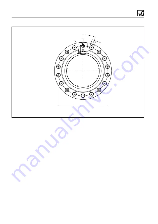
Page 57: ...nsions T40FH A4429 3 0 HBM public 55 22 5 16x22 5 360 395 10 5 Min bending radius R 20 30 5 75 5 18 Partial sections cut B B Dimensions in mm 1 mm 0 03937 Dimensions without tolerances per DIN ISO 276...
Page 58: ...13 2 2 T40FH 200 kNm 300 kNm 20 18x20 360 470 A A M36 230 150 40 40 99 4 10 B 540 540 345 g6 344 982 344 946 345 H7 345 057 345 000 12 B Partial sections cut A A Dimensions in mm 1 mm 0 03937 Dimensio...
Page 59: ...imensions T40FH A4429 3 0 HBM public 57 20 18x20 360 470 0 5 Min bending radius R 20 37 75 5 18 Partial sections cut B B Dimensions in mm 1 mm 0 03937 Dimensions without tolerances per DIN ISO 2768 mk...
Page 60: ...2 Components MF Complete measurement flange RO Rotor ST Stator N Not rotating Code Option 3 Accuracy S Standard linearity deviation including hysteresis 0 1 Code Option 4 Electrical configuration only...
Page 61: ...r rotational speed output Rotational speed connection cable 423 D Sub 15P 6 m 1 KAB150 6 Rotational speed connection cable 423 free ends 6 m 1 KAB154 6 Rotational speed with reference signal connectio...
Page 62: ...Mnom and 20 of Mnom 0 03 20 of Mnom and 60 of Mnom 0 065 60 of Mnom and 100 of Mnom 0 1 Voltage output For a max torque in the range between 0 of Mnom and 20 of Mnom 0 03 20 of Mnom and 60 of Mnom 0...
Page 63: ...sitivity tolerance deviation of the actual output quantity at Mnom from the nominal rated sen sitivity Frequency output 0 1 Voltage output 0 1 Output signal at torque zero Frequency output kHz 10 60 2...
Page 64: ...ut kHz 2 5 17 5 1 15 105 2 60 420 3 Voltage output V 12 12 Energy supply Nominal rated supply voltage DC safety extra low voltage V 18 30 Current consumption in measuring mode A 1 Current consumption...
Page 65: ...temperature range on the output signal related to the actual value of the signal span 0 1 on the zero signal related to nominal rated sensitivity 0 07 Relative standard deviation of reproducibility v...
Page 66: ...ength for signal deviations kA m 0 1 General information EMC Emission as per FCC 47 Part 15 Subsection C 7 Emission as per EN 61326 1 Section 7 RFI field strength Class B Immunity to interference EN 6...
Page 67: ...kNm 200 400 Breaking torque related to Mnom 11 kNm 300 600 Axial limit force 12 kN 230 290 Lateral limit force 12 kN 110 240 Bending moment limit 12 kNm 22 35 Oscillation width per DIN 50100 peak to p...
Page 68: ...peak Undulations in the connection flange area based on ISO 7919 3 Normal operation continuous operation m s p p 9000 n n in rpm Start and stop operation reso nance ranges temporary m s p p 13200 n n...
Page 69: ...y be permitted up to its specified load limit provided none of the others can occur at the same time If this condition is not met the limit values must be reduced If 30 of the bending moment limit and...
Page 70: ...g A 002 AB B 002 AB Flange A Flange B Hardness 46 54 HRC Surface quality of the axial and radial run out tolerances A B and AB 0 8 To ensure that the torque flange retains its characteristics once it...
Page 71: ...Mounting Instructions Montageanleitung English Deutsch T40FH...
Page 72: ...nnenring 18 5 5 Rotormontage vorbereiten 19 5 6 Montage des Rotors 22 5 7 Montage des Stators 25 5 8 Drehzahlmesssystem 30 6 Elektrischer Anschluss 32 6 1 Allgemeine Hinweise 32 6 2 EMV Schutz 32 6 3...
Page 73: ...schutz 50 13 Abmessungen 51 13 1 T40FH Drehmomentaufnehmer mit Drehzahlmesssystem Option 4 Code SU2 DU2 HU2 51 13 1 1 T40FH 100 kNm 150 kNm 51 13 1 2 T40FH 200 kNm 300 kNm 53 13 2 T40FH Drehmomentaufn...
Page 74: ...stallation des Produkts an anderer Stelle vorgegeben ist verwendet werden um die Einhaltung der FCC Vorschriften zu gew hrleisten Dieses Ger t entspricht Teil 15 der FCC Vorschriften Der Betrieb unter...
Page 75: ...10TOS11 IC 12438A T40S10TOS11 This device complies with part 15 of the FCC Rules Operation is subject to the following two conditions 1 This device may not cause harmful interference and 2 this device...
Page 76: ...areil ne doit pas causer d interf rence et 2 cet appareil doit accepter toute interf rence notamment les interf rences qui peuvent affecter son fonction nement Bestimmungsgem e Verwendung Der Drehmome...
Page 77: ...schinenelemente eingesetzt werden Bei dieser Verwendung ist zu beachten dass der Aufnehmer zu Gunsten einer hohen Messempfindlichkeit nicht mit den im Maschinenbau bli chen Sicherheitsfaktoren konstru...
Page 78: ...lagenplaner Ausr ster Betreiber so zu planen zu realisieren und zu verant worten dass Restgefahren minimiert werden Die jeweils existierenden natio nalen und rtlichen Vorschriften sind zu beachten All...
Page 79: ...itung dem Drehmoment Messflansch beizulegen Qualifiziertes Personal Qualifiziertes Personal sind Personen die mit Aufstellung Montage Inbe triebsetzung und Betrieb des Produktes vertraut sind und die...
Page 80: ...ebene Kennzeichnung zur Entsorgung Elektrische und elektronische Ger te die dieses Symbol tragen unterliegen der europ ischen Richtlinie 2002 96 EG ber elektrische und elektronische Altger te Das Symb...
Page 81: ...in die wenn die Sicherheits bestimmungen nicht beachtet werden leichte oder mittlere K rperverletzung zur Folge haben kann Hinweis Diese Kennzeichnung weist auf eine Situation hin die wenn die Sicherh...
Page 82: ...t durch seine kurze Bauweise u erst kompakte Pr faufbauten Dadurch ergeben sich vielf ltige Anwendungen Der Drehmomentflansch T40FH verf gt ber einen zuverl ssigen Schutz vor elektromagnetischen St ru...
Page 83: ...ng die bertragerspulen f r die ber hrungslose bertragung von Speisespannung und Messsignal Die Signale werden von einem teilbaren Antennenring gesen det bzw empfangen Der Antennenring ist auf einem Ge...
Page 84: ...14 A4429 3 0 HBM public T40FH Bei der Option 5 mit Drehzahlmesssystem ist auf dem Stator der Drehzahlsen sor montiert Die Drehzahlmessung erfolgt magnetisch mittels Feldplatten sensor und einem am Rot...
Page 85: ...fnehmers durch Resonanz berh hungen zu vermeiden S Stellen Sie sicher dass der Aufnehmer nicht berlastet werden kann WARNUNG Bei einer berlastung des Aufnehmers besteht die Gefahr dass der Auf nehmer...
Page 86: ...ur Pr fung ins Werk Darmstadt 5 2 Bedingungen am Einbauort Der Drehmoment Messflansch T40FH muss vor grobem Schmutz Staub l L sungsmitteln und Feuchtigkeit gesch tzt werden Der Aufnehmer ist in weiten...
Page 87: ...ssverst rker ein posi tives Ausgangssignal Bei der nichtdrehenden Ausf hrung ist bei Rechtsdrehmoment das Ausgangs signal in mV V positiv 5 4 Einbaum glichkeiten Da der Durchmesser kleiner ist als der...
Page 88: ...tem Antennenring Kundenseitige Befestigung 1 Rotor installieren 3 Ein Antennensegment demontieren 5 Stator ausrichten und fertig montieren 2 Statorbefestigung montieren 4 Antennensegment um den Wellen...
Page 89: ...orrichtungen Beachten Sie beim Arbeiten mit dem Kran die entsprechenden Sicherheitsvor schriften und tragen Sie Sicherheitsschuhe 1 Entfernen Sie die obere Schaumstofflage der Verpackung Abb 5 1 Verpa...
Page 90: ...n 3 Stellen Sie den Rotor auf einer sauberen stabilen Unterlage ab 4 Entfernen Sie eine Hebe se 5 Heben Sie den Rotor vorsichtig an bis er frei h ngt 6 Kippen Sie den Rotor vorsichtig beim Ablassen be...
Page 91: ...um Ro tor Abb 5 3 Rotor kippen 7 Sichern Sie den Rotor mit Keilen gegen Wegrollen 8 Schrauben Sie die zweite Hebe se wieder in die Gewindebohrungen in der Flanschau enfl che ein 9 Befestigen Sie den R...
Page 92: ...ist in der Regel das Rotor Typenschild verdeckt Deshalb liegen dem Rotor zus tzliche Klebeschilder mit den wichtigen Kenndaten bei die Sie auf den Stator oder andere relevante Pr fstandskomponenten a...
Page 93: ...u die Flanschplanfl chen des Aufnehmers und der Gegenflansche Die Fl chen m ssen f r eine sichere Drehmoment bertragung sauber und fettfrei sein Benutzen Sie mit L sungsmittel angefeuchtete Lappen ode...
Page 94: ...TITE in das Gegengewinde ein um einen Vorspannverlust durch Lockern auszuschlie en falls Wechsellasten zu erwarten sind Hinweis Halten Sie die maximale Einschraubtiefe nach Tab 5 1 Seite 24 unbedingt...
Page 95: ...n Tab 5 1 angegeben verwenden da dies den Reibfaktor beeinflusst 5 7 Montage des Stators Im Anlieferungszustand ist der Stator betriebsfertig montiert Sie k nnen das obere Antennensegment vom Stator t...
Page 96: ...eiben eingelegt sind diese sorgen f r einen definierten bergangs widerstand Wichtig Um eine einwandfreie Funktion zu gew hrleisten m ssen die F cherscheiben A5 3 FST DIN 6798 ZN verzinkt nach dreimali...
Page 97: ...S der Konstruktion des Maschinenbettes Wichtig Um Axialschwingungen zu vermeiden ist dem Drehmomentaufnehmer ein Klemmst ck beigelegt mit dem der Antennenring abgest tzt werden kann Hierzu befindet s...
Page 98: ...spiel f r die Abst tzung des Antennenrings 7 Befestigen Sie das klemmst ck mit der beigelegten Verschraubung nach Abb 5 8 Klemmen Sie ein geeignetes Abst tzelement z B einen Gewindestab 3 6 mm zwische...
Page 99: ...Mechanischer Einbau T40FH A4429 3 0 HBM public 29 Kundenseitige Abst tzung Klemmst ck Antennenring Abb 5 8 Abst tzen des Antennenrings Abb 5 9 Konstruktionsbeispiel f r Steckerklemmen f r zwei Stecker...
Page 100: ...momentaufnehmer mit Drehzahlmessung optional Wichtig Das Drehzahlmesssystem verwendet ein magnetisches Messprinzip Treffen Sie bei Anwendungen bei denen hohe magnetische Feldst rken auftreten k nnen z...
Page 101: ...ber der ber tragerwicklung des Rotors der Drehzahlsensor sich in der richtigen Position zum Zahnkranz des Rotors befindet Zahnkranz Drehzahlsensor Radialer Abstand Axiale Ausrichtung Abb 5 11 Seitenan...
Page 102: ...n Sie daher die Kabel in diesen F llen vor der Verlegung 6 2 EMV Schutz Wichtig Die Aufnehmer sind gem EG Richtlinien EMV gepr ft und mit einer CE Zerti fizierung gekennzeichnet Sie m ssen jedoch den...
Page 103: ...rungen durch Potenzialunterschiede Ausgleichsstr me auftreten trennen Sie am Messverst rker die Verbindungen zwischen Versorgungs spannungsnull und Geh usemasse und legen Sie eine Potenzialausgleichs...
Page 104: ...quenzausgang 5 V2 3 ws 13 5 2 Versorgungsspannung 0 V sw 5 3 Versorgungsspannung 18 V 30 V bl 6 4 Messsignal Drehmoment Frequenzausgang 5 V2 3 rt 12 10 5 Messsignal 0 V symmetrisch gr 8 6 6 Shuntsigna...
Page 105: ...nderen Fehlern in den Messverst r kern kommen Belegung Stecker 2 Drehzahl Messsystem 6 1 5 7 2 4 3 8 Ger testecker Draufsicht KAB154 KAB150 KAB1791 Stecker Pin Belegung Ader farbe D SUB Stecker Pin HD...
Page 106: ...gung Stecker Pin 8 Betriebsspannungsnull sw bl 3 8 6 Schirm an Geh usemasse 1 Br cke zwischen 4 9 2 Komplement re Signale RS 422 ab 10 m Kabell nge empfehlen wir einen Abschlusswiderstand mit R 120 Oh...
Page 107: ...4 3 Ger testecker Draufsicht Stecker Pin Belegung Aderfarbe 1 Messsignal Drehmoment Spannungsausgang 10 V ws 2 Versorgungsspannung 0 V sw 3 Versorgungsspannung 18 V 30 V bl 4 Messsignal Drehmoment Spa...
Page 108: ...ls Sie das Ger t an einem Gleichspannungsnetz1 betreiben m chten Die Hinweise dieses Kapitels beziehen sich auf den autarken Betrieb des T40FH ohne HBM Systeml sungen Die Versorgungsspannung ist von d...
Page 109: ...chalten 6 6 Versorgungsspannung Option 3 Code PNJ Als Zubeh r ist ein konfektioniertes 6 adriges Aufnehmer Anschlusskabel mit freien Enden erh ltlich Verl ngerungskabel sollten geschirmt und kapazit t...
Page 110: ...t Bestandteil der HBM Software MGCplus Setup Assistent Mit dem Editor k nnen Sie verschiedene Benutzerrechte verwalten und so die grundlegenden Aufnehmerdaten gegen versehentliches berschreiben sch t...
Page 111: ...Eine weltweit eindeutige TEDS Identifikationsnummer nicht nderbar Bereich 2 Der Basisbereich Basic TEDS dessen Aufbau durch die Norm IEEE 1451 4 definiert ist Hier stehen Aufnehmertyp Hersteller und S...
Page 112: ...e 0 0000m V V CAL Differenz dieser Werte ist der Kennwert laut HBM Pr fprotokoll oder aus Kalibrierung Maximum Electri cal Value 1 8245m V V CAL Mapping Method Linear Dieser Eintrag kann nicht ge nder...
Page 113: ...BM Datenblatt Calibration Date 1 Nov 2005 CAL Datum der letzten Kali brierung bzw Erstellung des Pr fprotokolls wenn keine Kalibrierung durch gef hrt bzw der Ein speicherung der TEDS Daten wenn ledigl...
Page 114: ...en 1 Beispielhafte Werte f r einen HBM Drehmoment Messflansch T40FH 150 kN m Template HBM Channel Name Channel name T40FH 150 kNm Beim Anlegen des Templates Bridge Sensor durch den Hersteller werden p...
Page 115: ...ignals sollte der Aufnehmer unbelastet sein da das Shuntsignal additiv aufgeschaltet wird Ausl sen des Shuntsignals Durch Anlegen einer Schutzkleinspannung von 5 30 V an Pin 6 und 7 am Stecker 1 oder...
Page 116: ...am Statorgeh use Wichtig Der Drehmomentaufnehmer ben tigt nach Anlegen der Versorgungsspannung noch bis zu 4 Sekunden bevor er betriebsbereit ist 9 1 Rotorstatus LED A obere LED Farbe Bedeutung Gr n p...
Page 117: ...geschaltet Lebendsignal damit ist das Funktionieren des Aufnehmers erkennbar 9 2 Statorstatus LED B untere LED Farbe Bedeutung Gr n dauerhaft leuchtend Messsignal bertragung und interne Stator Spannun...
Page 118: ...hmomente Beim Messen dynamischer Drehmomente ist zu be achten S Die f r statische Messungen durchgef hrte Kalibrierung des T40FH gilt auch f r dynamische Drehmomentmessungen S Die Eigenfrequenz f0 der...
Page 119: ...0 HBM public 49 0 Mnom 200 Schwing breite Mnom Nenndrehmoment Mnom in Zeit t Schwingbreite Schwingbreite Schwingbreite Abb 10 1 Zul ssige dynamische Belastung 11 Wartung Die Drehmoment Messflansche T4...
Page 120: ...em den europ ischen Vor schriften f r Umweltschutz und Rohstoffr ckgewinnung getrennt von regul rem Hausm ll zu entsorgen sind Da die Entsorgungsvorschriften von Land zu Land unterschiedlich sind bitt...
Page 121: ...ehmer mit Drehzahlmesssystem Option 4 Code SU2 DU2 HU2 13 1 1 T40FH 100 kNm 150 kNm Abmessungen in mm Ma e ohne Toleranzangaben nach DIN ISO 2768 mk 61 5 Montagema 10 17 15 6 5 Zur Axial sicherung 22...
Page 122: ...120 32 32 89 5 12 M30 30 5 12 10 450 395 450 395 282 260 g6 259 983 259 951 260 H7 260 052 260 000 27 53 432 16 44 95 5 95 H he Drehzahl sensor H he Geh use Ausbr che im Schnitt A A Abmessungen in mm...
Page 123: ...ublic 53 13 1 2 T40FH 200 kNm 300 kNm 85 Montagema 10 17 15 190 9 6 5 Zur Axialsicherung 22 18x20 360 576 5 564 5 280 ca 100 152 210 F r Anschlusskabel inkl Stecker A A Abmessungen in mm Ma e ohne Tol...
Page 124: ...50 40 40 112 12 M36 37 12 10 540 470 540 470 350 345 g6 344 982 344 946 345 H7 345 057 345 000 27 53 490 16 44 102 5 95 H he Drehzahl sensor H he Geh use Ausbr che im Schnitt A A 2 5 Abmessungen in mm...
Page 125: ...nehmer nicht drehend Option 4 Code PNJ 13 2 1 T40FH 100 kNm 150 kNm 22 5 16x22 5 360 395 A A M30 184 120 32 32 76 10 B 450 450 260 g6 259 983 259 951 260 H7 260 052 260 000 Ausbruch im Schnitt A A 12...
Page 126: ...Abmessungen 56 A4429 3 0 HBM public T40FH 22 5 16x22 5 360 395 10 5 Min Biegeradius R 20 30 5 75 5 18 Ausbruch im Schnitt B B Abmessungen in mm Ma e ohne Toleranzangaben nach DIN ISO 2768 mk...
Page 127: ...blic 57 13 2 2 T40FH 200 kNm 300 kNm 20 18x20 360 470 A A M36 230 150 40 40 99 4 10 B 540 540 345 g6 344 982 344 946 345 H7 345 057 345 000 12 B Ausbruch im Schnitt A A Abmessungen in mm Ma e ohne Tol...
Page 128: ...Abmessungen 58 A4429 3 0 HBM public T40FH 20 18x20 360 470 0 5 Min Biegeradius R 20 37 75 5 18 Ausbruch im Schnitt B B Abmessungen in mm Ma e ohne Toleranzangaben nach DIN ISO 2768 mk...
Page 129: ...onente MF Messflansch komplett RO Rotor ST Stator N Nicht rotierend Code Option 3 Genauigkeit S Standard Linarit tsabweichung einschl Hysterese 0 1 Code Option 4 Elektrische Konfiguration nur mit Opti...
Page 130: ...Anschlusskabel f r Drehzahl Ausgang Anschlusskabel Drehzahl 423 D Sub 15P 6 m 1 KAB150 6 Anschlusskabel Drehzahl 423 freie Enden 6 m 1 KAB154 6 Anschlusskabel Drehzahl mit Referenzimpuls 423 8 polig D...
Page 131: ...03 20 v Mnom und 60 v Mnom 0 065 60 v Mnom und 100 v Mnom 0 1 Spannungsausgang F r ein max Drehmoment im Bereich Zwischen 0 v Mnom und 20 v Mnom 0 03 20 v Mnom und 60 v Mnom 0 065 60 v Mnom und 100 v...
Page 132: ...e bei Mnom vom Nennkenn wert Frequenzausgang 0 1 Spannungsausgang 0 1 Ausgangssignal bei Drehmoment Null Frequenzausgang kHz 10 60 240 Spannungsausgang V 0 Nennausgangssignal Frequenzausgang bei posit...
Page 133: ...fnahme im Messbetrieb A 1 Stromaufnahme im Anlaufbetrieb A 4 typ 2 50 s Nennaufnahmeleistung W 10 Maximale Kabell nge m 50 Shuntsignal ca 50 von Mnom Toleranz des Shuntsignals bezo gen auf Mnom 0 05 N...
Page 134: ...DIN 1319 bezogen auf die Ausgangssignal nderung 0 02 Eingangswiderstand bei Referenz temperatur 1560 100 Ausgangswiderstand bei Referenz temperatur 1400 100 Referenzspeisespannung V 5 Gebrauchsbereic...
Page 135: ...nkst rfeldst rke Klasse B St rfestigkeit EN 61326 1 Tab 2 Elektromagnetisches Feld AM V m 10 Magnetisches Feld A m 100 Elektrostatische Entladungen ESD Kontaktentladung kV 4 Luftentladung kV 8 Schnell...
Page 136: ...breite nach DIN 50100 Spitze Spitze 13 kNm 200 400 Oberes maximales Drehmoment kNm 150 300 Unteres maximales Drehmoment kNm 150 300 Mechanische Werte Baugr e BG1 BG2 Drehsteifigkeit cT kN m rad 119310...
Page 137: ...ormalbetrieb Dauerbetrieb m s p p 9000 n n in min 1 Start und Stoppbetrieb Resonanz bereiche tempor r m s p p 13200 n n in min 1 Massentr gheitsmoment des Rotors Iv um Drehachse ohne Ber cksichti gung...
Page 138: ...des Nenndrehmoments ist bis zu der angegebenen Belastungsgrenze nur dann zul ssig solange keine der jeweils anderen von ihnen auftreten kann Andernfalls sind die Grenzwerte zu reduzieren Wenn je 30 de...
Page 139: ...trierung A 0 02 AB B 0 02 AB Flansch A Flansch B H rte 46 54 HRC Oberfl cheng te der Plan und Rundlauffl chen A B und AB 0 8 Um die Eigenschaften des Drehmoment Messflanschs im eingebauten Zustand zu...
Page 140: ...www hbm com HBM Test and Measurement Tel 49 6151 803 0 Fax 49 6151 803 9100 info hbm com measure and predict with confidence A4429 3 0 7 2002 4429 HBM public...