Propeller Owner’s Manual
147
INSTALLATION AND REMOVAL
61-00-47
Page 3-28
Rev. 17 Sep/20
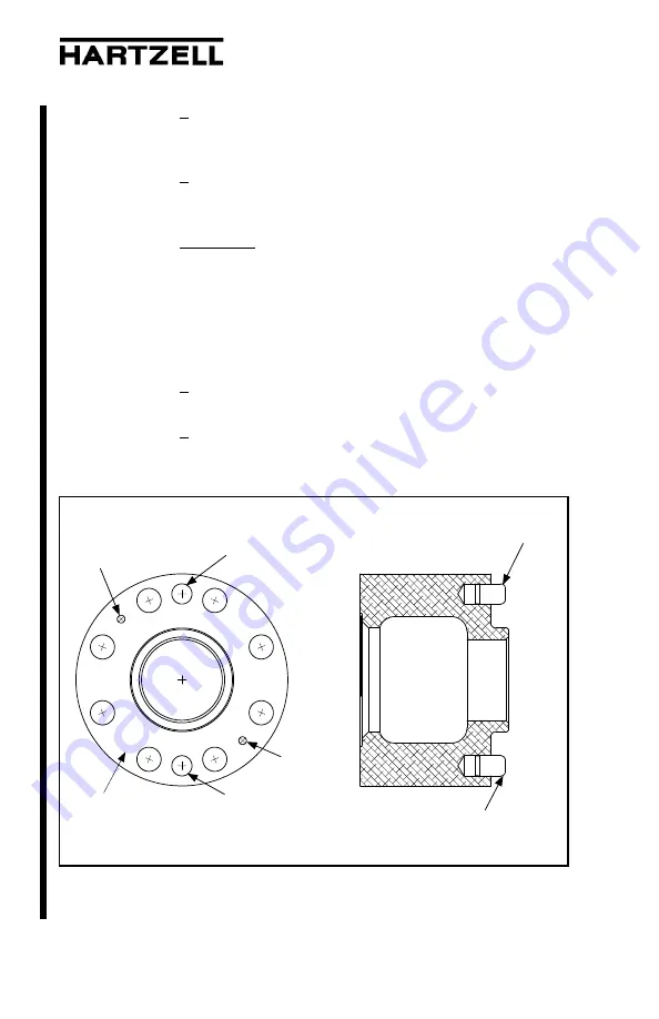
2 Install the hub-to-spacer O-ring in the groove in
the spacer that interfaces with the face of the
hub flange. Refer to Figure 3-8
.
3 Align the mounting studs and dowel pin holes in
the propeller hub flange with the mounting holes
and dowel pins in the spacer.
CAUTION:
MAKE SURE THAT THE
HUB-TO-SPACER O-RING STAYS
IN THE GROOVE IN THE SPACER.
IF THE O-RING IS TWISTED OR
PINCHED, OIL LEAKAGE WILL
RESULT WHEN THE PROPELLER
IS OPERATED ON THE AIRCRAFT.
4 Put the spacer onto the mounting studs and
against the hub flange.
5
If the hub flange has two 8-32 threaded holes
and two B-3868-S60 screws are provided to
attach the 106943 spacer, install the screws.
Dowel pin
Attachment
screw hole
Propeller
Side
Engine
Side
Dowel pin
Attachment
screw hole
Hub-to-Spacer O-ring Location in the Spacer
Figure 3-8
TPI-L
W
-147-00617
Dowel pin
Dowel pin
Engine Side


