18
HAN 1/5 Spitfi re Mk IXc 30cc
17
L
R
L
R
x8
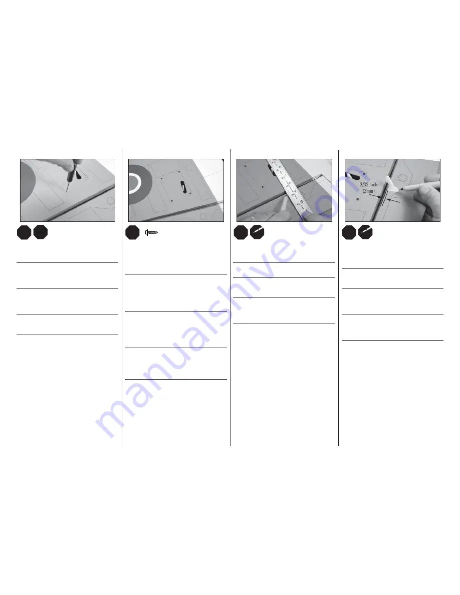
Place the aileron servo hatch into position. Use a pin vise
and 1/16-inch (1.5mm) drill bit to drill the holes in to the
mounting tabs using the holes in the hatch as a guide.
Setzen Sie die Querruderservoabdeckung wieder auf. Bohren
Sie mit einem 1,5mm Handbohrer die Befestigungslöcher in
die Montageleiste und nutzen die Löcher in der Abdeckung als
Lehre.
Placez la trappe de servo d’aileron en position. Utilisez un
foret de 1.5mm pour percer les trou de fi xation dans les
languettes de l’aile, utilisez l couvercle comme guide de
perçage.
Rimettere in posizione il coperchio del portaservo alettoni. Con
una punta da 1,5mm praticare i fori sulle alette di fi ssaggio,
usando i fori del coperchio come guida.
18
L
R
L
R
M2 x 10
x4
Remove the aileron servo hatch from the wing. Thread a screw
into each of the holes in the aileron servo hatch mounting
holes. Remove the screws before proceeding. Apply a small
amount of thin CA to harden the threads. Secure the servo
cover to the wing using four M2 x 10 self-tapping screws.
Nehmen Sie die Querruderservoabdeckung von der Tragfl äche
ab. Drehen Sie eine Schraube in jedes der Befestigungslöcher
und wieder heraus. Geben Sie zum härten der Gewinde eine
kleine Menge dünnfl üssigen Sekundenkleber in die Löcher.
Die Querruderservoabdeckung wird mit vier M2 x 10 selbst-
schneidenen Schrauben gesichert.
Retirez de l’aile la trappe d’aileron. Visser une vis dans
chacun des trous de fi xation de la trappe du servo d’aileron.
Enlever les vis avant de poursuivre. Appliquer une petite
quantité de colle cyano fi ne pour durcir les fi letages taillés
lors de l’étape précédente. Fixer la trappe de servo à l’aide de
4 vis auto-taraudeuses M2 x 10.
Togliere dall’ala il coperchio per il portaservo alettoni. Avvitare
una vite in ogni foro per il fi ssaggio del servo. Togliere le viti e
mettere nei fori una piccola quantità di colla CA per indurire
il fi letto. Fissare all’ala il coperchio del portaservo con 4 viti
autofi lettanti M2x10.
19
L
R
L
R
Place a ruler along-side the servo horn. With the ruler
perpendicular to the hinge line, mark the location for the
control horn on the aileron.
Richten Sie ein Lineal rechtwinklig zum Servohorn aus und
markieren die Position des Querruderruderhorns.
Placez une règle contre le bras de servo, la règle à
la perpendiculaire de la ligne de charnière, marquez
l’emplacement du guignol sur l’aileron.
Posizionare un righello lungo il fi anco della squadretta del
servo. Tenendo il righello perpendicolare rispetto alla linea
della cerniera, segnare la posizione per la squadretta di
controllo sull’alettone.
20
L
R
L
R
Position the control horn at the mark made in the previous
step. Set the control horn back from the bevel 3/32 inch
(2mm). Mark the locations for the control horn mounting
screws.
Positionieren Sie das Ruderhorn an der Markierung und 2mm
von der Kante entfernt. Markieren Sie die Positionen für die
Bohrlöcher.
Placez le guignol sur les marques tracées à l’étape
précédente. le guignol doit être placé 2mm en arrière de
l’arrête de l’aileron. Marquez les emplacements des vis de
fi xation.
Posizionare la squadretta di controllo sul segno fatto nel
passaggio precedente. Posizionare la squadretta di controllo 2
mm dietro alla ruota dentata. Segnare le posizioni per le viti di
montaggio della squadretta di controllo.


