


21
/
97
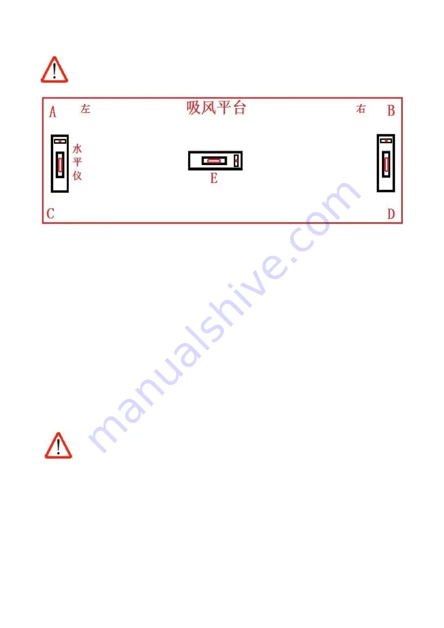
When adjusting the level on the right/left side, the level should face the same direction.
水平仪放置位置示意图
1. There are 6 main supporting foot cups on the machine body. First, raise up all the foot cups, and lower
down the 4 foot cups in the corner of the frame, make sure they touch the ground. Jack up the foot cups
until the yellow base leave the ground (5mm height would be enough)
2. Place the level on E position, check the height difference of left/right side
3. Place the level between position A and C, or between position B and D, check for the height for A,B,C,D
points, then adjust the foot cup height according to the reference from step 2.
4. Adjust the 4 points to the same level with the assist of level, lock the foot cup screw to prevent loose
5. After the level adjustments, remove the yellow bases, lower down all the foot cups to the ground, lock
the screws
6. Check the machine level again (Do not raise the foot cup too high, in case the machine shakes when
running)
After adjusted the level, check for the error direction should be in the same direction (No more
than 1 unit on the measure ruler) as below diagram shows.
Summary of Contents for HT3020UV-C-K
Page 1: ...HandTop Flatbed Ink Jet Printer Operation Manual HT3020UV C K...
Page 15: ...14 97...
Page 16: ...15 97...
Page 18: ...17 97 1 Pre installation 2 1 Prepare the working field under previous instruction...
Page 27: ...26 97 Steps 1 check the parts Guide rail stand x2 Rear bearing standx2...
Page 29: ...28 97 B Put the screw on the stand 8 pcs C Insert two bolts...
Page 30: ...29 97 D Mount the guide rail screw E Tighten all the screws...
Page 39: ...38 97 The latest Topjet version only support 64bit Select communication way...
Page 40: ...39 97 Select equipment model Select print head DPI...
Page 41: ...40 97 Select print head row s...
Page 42: ...41 97 Select UV lamp type Select Topjet directory C drive is not recommended...
Page 43: ...42 97 Select shortcut Finish...
Page 44: ...43 97...
Page 45: ...44 97 Select Agreed to proceed Finish Install USB communication driver...
Page 46: ...45 97 Accept and Next Next...
Page 47: ...46 97 Finish reboot the PC...
Page 51: ...50 97 5 2 3 Printing mode interface...
Page 56: ...55 97 to the right...
Page 58: ...57 97...
Page 60: ...59 97 Ink tube and filter connection Print head connector...
Page 61: ...60 97 Preparation Flush ink tubes with flushing liquid...
Page 62: ...61 97 Disconnect the block...
Page 63: ...62 97 Connect ink tubes Next...
Page 64: ...63 97 Ink tube installation finished Dismount the protective cover of the print head...
Page 81: ...80 97 7 13 Base of spot Print with white spot as a base layer of other colors...


