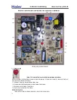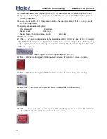
When LED is used as a status indicator, the following codes will be shown:
1.5 In defrost, the LED will flash 2 seconds on, 2 senconds off.
1.6 In the normal operation state and the compressor is running – outdoor PCB LED will be in the ON state.
1.7 In normal state, if compressor not running – outdoor PCB LED wiil be OFF.
2. Function selection
Function selection for SW1:
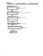
2.1 SW1-1: ON-quick defrosting mode, used for very cold area, please see 5.2
OFF-default setting, normal defrost program, please see 5.1
2.2 SW1-2: ON-temperature point from which begin to count for defrost Tp<32
℉
OFF- temperature point from which begin to count for defrost Tp<35.6
℉
The setting for SW1-1, SW1-2 when out of factory: OFF, OFF.
2.3 Combinatoin of SW1-3, SW1-4:
OFF-OFF: current protection value 1
OFF-ON: current protection value 2
ON- OFF: current protection value 3
ON-ON: current protection value 4
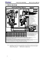
The above current values are set when the equipment is shipped from factory, and they will be
different values for different models. For the relationship between the dip switch setting and the
compressor winding circles accross CT, please refers to the wiring diagram with the unit.
3.1 Outdoor coil temp. sensor: R25=5K
Ω
, B25/50=3450K, with copper terminal
T(
℉
)
Rnom(K
Ω
)
T(
℉
)
Rnom(K
Ω
)
T(
℉
)
Rnom(K
Ω
)
T(
℉
)
Rnom(K
Ω
)
T(
℉
)
Rnom(K
Ω
)
-4 47.12
28.4
19.39
60.8
7.661 93.2 3.368 125.6 1.667
-2.2 45.17 30.2 18.39 62.6 7.295 95 3.23 127.4 1.608
-0.4 43.24 32 17.45
64.4
6.949 96.8 3.098 129.2 1.551
1.4 41.35 33.8 16.55
66.2
6.622 98.6 2.973 131 1.457
3.2 39.49 35.6 15.7 68 6.313 100.4 2.845 132.8 1.445
5 37.68 37.4 14.89 69.8 6.021 102.2 2.741 134.6 1.395
6.8 35.92 39.2 14.13
71.6
5.744 104 2.633 136.4 1.347
8.6 34.21 41 13.41
73.4
5.482 105.8 2.536 138.2 1.301
10.4 32.56 42.8 12.73 75.2 5.235 107.6 2.432 140 1.257
12.2 30.37 44.6 12.08 77
5 109.4
2.339
14 29.44
46.4
11.47
78.8 4.778 111.2 2.25
15.8 27.57 48.2 10.9 80.6 4.567 113 2.165
17.6 26.57 50 10.35
82.4 4.36 114.8 2.084
19.4 25.22 51.8 9.837 84.2 4.179 116.6 2.006
21.2 23.94 53.6 9.351 86 3.993 118.4 1.932
23 22.72
55.4
8.892
87.8 3.819 120.2 1.862
24.8 21.55 57.2 8.458 89.6 3.657 122 1.793
26.6 20.45 59 8.048
91.4 3.514 123.8 1.729
3. Parameters value of temp. sensors
35
Central Air Conditi
oning
Model: Heat Pump,
HR13-D1


