they indicate the cubic feet of air per minute(CFM)
moving through the coil.
An inclined manometer
or
magnehilic guage can be used for measurement
.
A velometer measures the velocity of the air in feet per minute(FPM). If the area of duct is known,
▼
1.08
×
TEMP RISE
COMPRESSOR AND SYSTEM FAULT DIAGNOSIS
misdiagnosed.To ensure that does no t happen, the
technician must determine if the compressor
has
problem. The following procedures should help
determine if the compressor has failed.
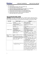
COMPRESSOR ELECTRICAL CHECKS
lower resistance and connects directly to the power supply
from the compressor contactor.
2
.
Measure the available line voltage .
A. This could indicate high or low voltage problems or improper start components.
B. check the contactor coil with an ohmmeter for a short or open circuit.
C. Replace the contactor if any fault is noted.
5
.WITH THE ELECTRICAL POWER OFF
, remove all power wires from the compressor
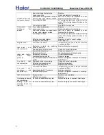
A. Use an ohmmeter set for the highest scale to check for grounding between compressor motor
terminals and a good clean ground such as the compressor shell or copper line.
B. The resistance from any terminal to ground should exceed 1,000,000 ohms.
6.Use an ohmmeter set for the lowest scale and check the continuity of the motor windings .These
ohm values are less than ten ohms and in some cases less than one ohm.
to suffers lack of dehumidify in cooling. insufficient air flow while cooling may result in coil freeze up,
excessive dehumifification and lost capacity.
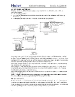
rrovided to show how to measure pressure drop across the
coil. If pressure drop tables are available,
the velometer reading times the area of duct (in square feet ) calculates the air flow.
Checking air flow is the most important diagonistics a service technican can perform. Instructions are
If the indoor unit has an electrical heater, air flow can be estimated by measuring the air temperature
TS
×
AMPS
×
3.414
entering and leaving the heater and calculating the CFM.
Compressor manufacturers state that maul of the compressors returned as defective have been
failed or if another control has either failed or
stopped the compressor
from operating
after detecting a
Prior to replacing a suspected failed compresso
,
a thorough check must be made of all existing electrical
electrical components .If not done ,a replacement compressor might also failed or not operate at all
WARNING: THE FOLLOWING PROCEDURES SHOULD ONLY BE ATTEMPTED BY QUALIFIED SERVICE TECHICIANS
EQUIPPED WITH PROPER TOOLS, SAFTY PROCEDURES AND EQUIPMENT AND INSTRUMENTS TO PERFORM
winding has the higher resistance and is connected in series with the
capacitor. The run winding has the
THE DESCRIBED REPAIRS.
Single-phase compressors use permanent split capacitor motors. There are two windings that
connect at
a common point at the “common” wiring terminal. The two windings are called “start”
and "run". The start
ELECTRICAL CHECK COMPRESSORS
The design uses a protective device called an “internal overload”. If compressor draws high amperages,
for an anusually long time or temperatures in the compressor motor, it opens an internal circuit to stop
the motor.
On the single phase 208/230Volt units ,this should be from 197 to
253
Volts.
1
.
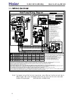
Consult the unit wiring diagram. Confirm that all electrical wiring for the units is correct and that
all wiring connections are right.
3. Check for proper control voltage at the unit contractor coil . If this voltage is inadequate or is not
section for possible causes.
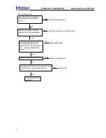
present, refer to the wiring diagram or the compressor troubleshooting flow chart at the end of this
4. Disconnect all power from the unit and visually inspect the compressor contactor for pitted or
burned contacts.
A .The ohm reading from the RUN terminal to common terminal is the lowest reading measured between.
compressor terminals, approxiamtely 1 ohm.
28
terminals,
MARK THE ORIGINAL LOCATION OF EACH WIRE.
Central Air Conditi
oning
Model: Heat Pump,
HR13-D2
CFM
(Electrical Heater) =
VOL

