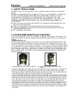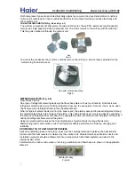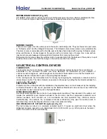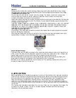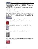
8.10.SYSTEM STARTUP
1.Turn thermostat to "OFF", turn on power supply at disconnect switch.
3.Turn fan switch to "ON". Indoor blower should run. Be sure it is running in the right direction.
4.Turn fan switch to "AUTO". Turn system switch to "COOL" and turn temperature setting below
room temperature. Unit should run in cooling mode.
6.Check the refrigerant charge (see Instructions under "Charging the System").
7.Replace service port caps. Service port cores are for system access only and will leak if
not tightly capped.
9.Instruct the owner on operation and maintenance.
Leave this "Installation and Operating Manual" and the "Use and Care Manual" with owner.
8.11.OPERATION
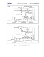
SEQUENCE OF OPERATION
COOLING CYCLE
1.
2.
The vapor leaves the compressor and passes through the reversing valve.
4.
pressure and temperature .
6.
7.
8.
accumulator.
repeats.
1.
2.
3.
indoor blower starts.
4.
5. The thermostat satisfies and ends the call for cooling.
6. This ends the 24 Voltage signal to the compressor start kit and the outdoor unit stops.
7. This ends the 24 voltage signal to the indoor blower relay and this indoor blower strips
8. The system is now off.
The cooling system is now in operation.
The liquid, under reduced pressure, then enters the indoor coil surface it expands and absorbs
heat from the indoor air passing over the finned surface. Heat from the indoor air, causes the low
pressure liquid to evaporate and cool the indoor air. The refrigerant has now been converted to cool vapor.
Electrical .
The operation cycle as follows:
The accumulator separates any liquid refrigerant and holds it. Only vapor refrigerant and
The thermostat calls for cooling when the space temperature is above the set point.
This sends a 24 voltage signal through the “Y” terminal to the outdoor unit PCB, after 3 minutes
the compressor contact in the outdoor unit are closed. The compressor and outdoor fan start.
At the same time, a 24 Voltage signal flows through the “G” Terminal to the air handler PCB and
8.Check unit for tubing and sheet metal rattles.
2.Turn temperature setting above the room temperature.
5.Check to see if compressor and outdoor fan are running correctly.
In order to service and troubleshoot a air conditioning system, The service technician must
5. At the end of the liquid line, the refrigerant passes through a fixed metering device, reducing
understand the system’s sequence of operation. This is the order of events the system undergoes in
response to. Understanding the sequence of operation aid in determining where to start troubleshooting
when the unit doesn’t operate properly. Deviation from the normal operation sequence will provide
3. The vapor flows through the outdoor vapor line to the finned outdoor coil. Air from the outdoor
clues to system problems.
Mechanical
.
The operation sequence is as follows:
fan removes heat from the refrigerant vapor. When enough heat is removed, the vapor
condenses into a high pressure liquid.The liquid temperature leaving the outdoor coil is slightly
This warm, high pressure liquid leaves the outdoor coil, and flows through the small copper
The compressor provides high pressure, superheated refrigerant vapor.
warmer than ambient air temperature.
The cool refrigerant vapor travels through the larger, insulated vapor line to the accumulator.
refrigerant oil leave the accumulator. The oil is drawn out through a special port inside the
9. Refrigerant vapor flows through the suction line to the intake of the compressor. The cycle then
22
refrigerant liquid line.
Central Air Conditi
oning
Model: Heat Pump,
HR13-D2

