4.
Causes
:Leaking liquid line valve, leaking discharge check valve (scroll compressors only ),
Refrigerant is leaking from the
condenser coil .
Causes
:Leaking liquid line valve, leaking discharge check valve (scroll compressors only ),
leaking compressor valves.
ACTION
: Determine the causes and correct it..
This procedure checks the quality of the refrigerant by comparing the refrigerant pressure to its
SHUT Down the system when the suction pressure drops to 3-5 psi positive pressure .
2. Front SEAT THE LARGE VAPOR LINE VALVE.
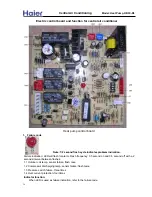
MARK AND IDENTIFY THE WIRE TERMINALS
WITH THE COPRESPONDING WIRE COLOR CODE
.
WARNING :WRAP A LAYER OF INSULATION ELECTRICAL TAPE OVER THE WIRE TERMINALS ,
4.
5.
is now the refrigerant temperature .
6.
After pump down and compressor stops, observe the suct
io
n pressure on the compound gauge.
A. The suction pressure holds as steady pressure.
this is a normal condition.
. Refrigerant is leaking from the condenser coil .
B. Suction pressure rises above the stopping point, but then stops and holds steady. Some refrigerant
ACTION
: Determine the causes and correct it.
finally evaporating in the coil, and registering on the gauge.
This is the normal condition.
C. Suction pressure conditions rise and eventually equalizes with the observed pressure on the high
leaking compressor valves.
Abnormal condition.
pressure guage.
D
. Unable to reach the 3-5 PSI level for suction pressure.
This is an abnormal condition.
SYSTEM REFRIGERANT NONCONDENSIBILES CHECK
temperature. The test tells if there are contaminating non-condensable gases in the refrigerant, usually
air or moisture.
1. Pump the system down as the explained in the previous procedure. Open the unit disconnect to
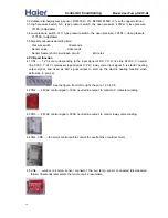
3. Disconnect the compressor by
REMOVING EACH WIRE FROM THE COMPRESSOR
TERMINALS.
(NOT THE COMPRESSOR TERMINALS) . THESE WIRE ENDS WILL BE AND GNERGISED HOT
DURING THE REMINDER OF THE TEST .
Run the condensing fan until the leaving air temperature equals to the entering air temperature. This
Close the disconnect switch to the system and run the condensing fan .Measure the condensing coil
Compare the observed refrigerant pressure shown on the high pressure gauge to its associated pressure
entering and leaving air temperature with accurate thermometers.
on a temperature –pressure conversion chart.
7. The refrigerant pressure should equal the chart pressure for the observed temperature.
A. The system pressure is above the chart pressure. Capital letters: Non-condensales are present
-air and/or moisture.
ACTION:
Remove and recover the refrigerant. Evacuate the system and
B. The system pressure is below the chart pressure.
C
apital letters: A mixed refrigerant is
charge with new and correct refrigerant.
and correct refrigerant.
present.
ACTION:
Remove and recover the refrigerant. Evacuate the system and charge with new
COMPRESSOR REMOVAL PROCEDURES
Use the following procedure for compressor removal ONLY after determining that the compressor has
failed.
USE THESE PROCEDURES ONLY WHEN YOU HAVE POSITIVELY DETERMINED THAT THE
COMPRSSOR HAS EXPERIENCED A MECHANICAL AND/OR ELECTRICAL FAILURE.
should wear rubber gloves and eye protection to prevent injury when testing refrigerant oil.
1. DISCONNECT THE MAIN POWER SOURCE TO THE UNIT AND LOCK THE DISCONNECT
2.
3.
Disconnect the electrical wiring at the compressor identifying each wire and its location.
SWITCH IN THE OPEN POSITION.
Remove the refrigerant charge from the entire system using proper recovery procedures.
CAUTION: After a seveer motor burn-out the products of the burn-out may be acidic. The technician
30
Central Air Conditi
oning
Model: Heat Pump,
HR13-D2


