66
Inputs/Outputs Menu
Analog output characteristics (continued)
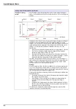
“Tri-linear” analog
output
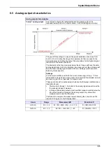
The "Tri-linear" output brings benefits over the “Linear output” discussed
before. It is illustrated below (4-20 mA output is shown, 0-20 mA settings are
similar).
Compared to the “Linear” mode, the expected range of measure is Range 2.
A Range 1 and 3 are available to show the measures falling out of this
Range 2, but normally at a lower resolution. Expected measurements for the
measured process are supposed to be in Range 2 most of the time, and in
Range 1 or 3 occasionally (problems, calibration, line stop, etc.). The
benefits are:
•
The PLC can compute the measurement over a large range (1, 2 and 3).
•
The PLC can compute a higher resolution signal for the expected
measuring range (Range 2: MH > M > ML).
•
Carefully selecting the set points allows for an individual resolution for
each range, so a different resolution can be applied to Range 1, 2 and 3,
allowing to tailor the analog output to the actual conditions.
As before, the downside is that any measure below or over the Range 1, 2
and 3 will have the same signal locked at 4 mA and 20 mA respectively, but
Range 1, 2 and 3 should cover a larger range than in the “Linear” mode.
Settings must made in balancing these aspects.
Settings
For each output, set MLL, ML, MH, and MHH in the current measuring unit
(e.g. °C for a temperature output). When a compound unit is selected, the
smallest unit will be used (e.g. ppb for a "ppm-ppb" compound unit). Also set
AOL (Analog Output Low) and AOH (High) in mA.
These points should be set keeping in balance the following conditions (see
illustration above):
•
The smaller is Range 2, the better is the analog signal resolution within
the expected range of measure.
•
Size of Range 1 and 3 should be set to deliver an adequate level of
resolution for the measures falling out of the expected range of
measure.
•
In Range 0 the analog outputs only shows that measurement is below
the MLL value. Similarly in Range 4 the analog output only shows that
measurement is over the MHH value.
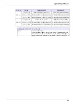
The formula to compute the measurement knowing the current and the
resolution R is given in the following table:
Summary of Contents for ORBISPHERE K1200
Page 5: ...4 Table of Contents...
Page 13: ...12 General Information...
Page 39: ...38 Installation...
Page 45: ...44 User Interface...
Page 46: ...45 Section 5 View Menu Figure 34 View menu...
Page 49: ...48 View Menu...
Page 59: ...58 Calibration Menu...
Page 60: ...59 Section 8 Inputs Outputs Menu Figure 40 Inputs Outputs menu...
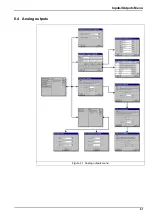
Page 62: ...61 Inputs Outputs Menu 8 4 Analog outputs Figure 41 Analog outputs menu...
Page 69: ...68 Inputs Outputs Menu...
Page 86: ...85 Section 11 Products Menu Figure 44 Products menu...
Page 89: ...88 Global Configuration Menu...
Page 90: ...89 Section 13 Services Menu Figure 46 Services menu Part 1...
Page 91: ...90 Services Menu Figure 47 Services menu Part 2...

