27
Installation
3.5 Connectors assembly instructions
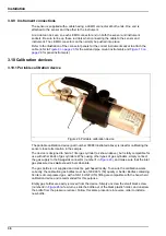
3.5.1 Cable gland wiring instructions
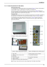
A waterproof cable gland is provided each time a cable must be connected inside the
instrument. The nickel-plated brass cable glands are EMC-types, designed so that the cable
shields attach directly to the instrument housing as a ground. Typical cable wiring instructions
are detailed below.
1.
Unscrew the cable gland nut. Inside, the assembly is composed of a rubber gasket, and two
metal washers. Note that the ethernet gland on panel and wall mount instruments does not
have washers and the gasket is cut.
2.
If wiring a sensor cable, the cable has already been prepared so simply remove the piece of
plastic protection from the exposed shielding.
For other cables, strip off external insulation as required, and 25 mm of shielding. Strip the
wires about 8 mm from their ends (see illustration below).
3.
Pass the cable through the nut, the rubber gasket, and the two washers
4.
Pinch the shield so that its entire circumference is pressed between the two washers and
pass the cable into the housing, blocking the cable gland
5.
Reattach and tighten the cable gland nut
6.
Attach the wires to the corresponding terminal block connections
WARNING
Potential Electrocution Hazard. In order to maintain the NEMA/IP environmental
ratings of the enclosure, use only conduit fittings and cable glands rated for at least
NEMA 4X/IP65 to route cables into the instrument.
Gland parts (washers not shown):
1.
Nut
2.
Rubber gasket (seal)
3.
Gland fitting with O-ring (attached to
instrument housing)
NOTICE
It is vitally important to ensure the shielding is pinched and secured between the two washers
to ensure the shielding attaches directly to the instrument housing as a ground. Failure to do
this could cause damage to the instrument, and for sensor cables give incorrect readings.
Summary of Contents for ORBISPHERE K1200
Page 5: ...4 Table of Contents...
Page 13: ...12 General Information...
Page 39: ...38 Installation...
Page 45: ...44 User Interface...
Page 46: ...45 Section 5 View Menu Figure 34 View menu...
Page 49: ...48 View Menu...
Page 59: ...58 Calibration Menu...
Page 60: ...59 Section 8 Inputs Outputs Menu Figure 40 Inputs Outputs menu...
Page 62: ...61 Inputs Outputs Menu 8 4 Analog outputs Figure 41 Analog outputs menu...
Page 69: ...68 Inputs Outputs Menu...
Page 86: ...85 Section 11 Products Menu Figure 44 Products menu...
Page 89: ...88 Global Configuration Menu...
Page 90: ...89 Section 13 Services Menu Figure 46 Services menu Part 1...
Page 91: ...90 Services Menu Figure 47 Services menu Part 2...


