3-3
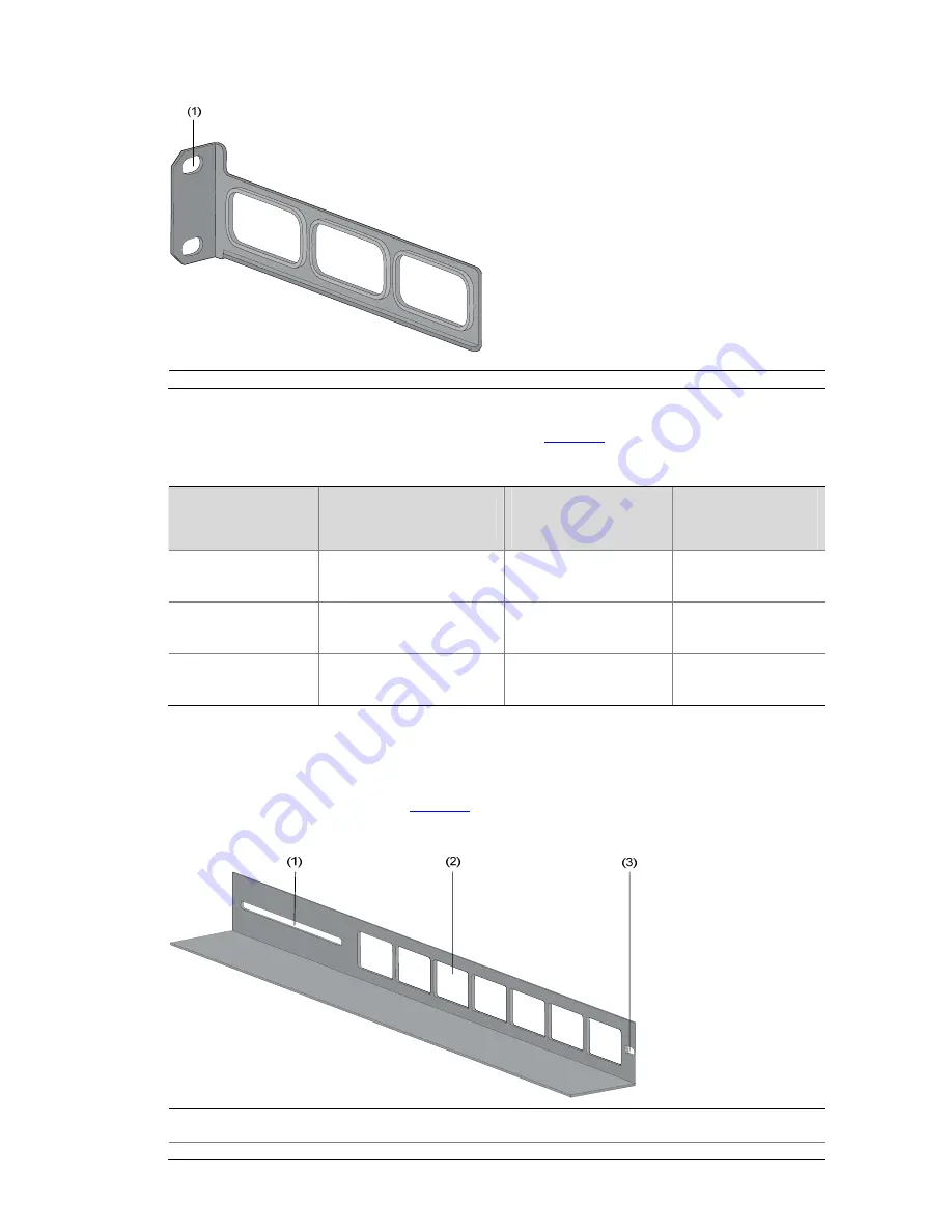
Figure 3-3
Appearance of a rear mounting bracket
(1) Screw hole used to fix the mounting bracket to the cabinet (Use one M6 screw)
For the selection of front and rear mounting brackets, see
Table 3-2
.
Table 3-2
Selection of mounting bracket for S5500-SI Series Ethernet switches
Model
Physical dimensions (H
× W × D)
Configuration type of
front mounting
bracket
Configuration type
of rear mounting
bracket
S5500-28C-SI
S5500-52C-SI
43.6 × 440 × 300 mm
(1.72 × 17.32 × 11.81 in.)
Standard —
S5500-20TP-SI
43.6 × 440 × 360 mm
(1.72 × 17.32 × 14.17 in.)
Standard Standard
S5500-28C-PWR-SI
S5500-52C-PWR-SI
43.6 × 440 × 420 mm
(1.72 × 17.32 × 16.54 in.)
Standard Standard
Introduction to Guide Rail
Guide rails are optional parts. Check
Table 3-1
to see whether you need to order them or not.
Figure 3-4
Appearance of a guide rail
(1) Slotted hole 1: Used to fix the guide rail to the rear post. You can adjust the screw hole position
according to the position of the switch.
(2) Cooling hole: Used for heat dissipation between switch and cabinet


