


3-13
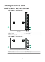
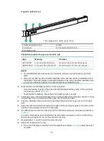
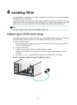
Mounting the switch in a rack
CAUTION:
•
Hold the chassis handles to move the switch. Do not hold the handle of a fan tray, a power
module, or a module, or the air vents of the chassis to carry the switch. Any attempt to carry the
switch with these parts might cause equipment damage or even bodily injury.
•
Remove the fan trays, power modules, and filler panels from the switch before lifting. Reinstall
these components after installing the switch in the rack.
•
Do not place your hand into any slot when you move the chassis.
IMPORTANT:
•
The switch is heavy. As a best practice, use a mechanical lift, such as forklift truck, to move and
carry the switch to the rack.
•
If no mechanical lift is used, cooperate with a minimum of four people to manually lift the switch.
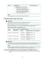
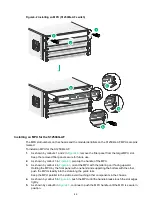
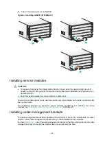
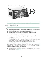
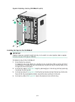
To mount the switch in a rack:
1.
Orient the chassis with its rear facing towards the front of the rack.
2.
Lift the chassis until the switch bottom is a little higher than the slide rails on the rack.
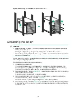
3.
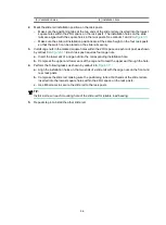
Facing the front of the rack, place the switch on the slide rails and slide the switch into the rack
along the slide rails until the mounting brackets are flush against the front rack posts, as shown
in
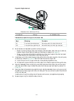
After placing the switch on the slide rails, do not leave go of your hands immediately because
this might tip the switch, damaging the switch or even causing bodily injury.
4.
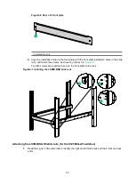
Use M6 screws provided with the switch to attach the mounting brackets to the rack posts.
The name plate on the upper right corner of the front panel covers two mounting screw holes in
the mounting brackets. Screws are not needed for these two mounting holes.
If the mounting holes in the mounting brackets cannot align with the cage nuts on the rack,
verify the following items:
The top flange of the slide rail aligns with the middle of the narrower metal area between
holes.
The cage nuts are installed in the correct holes.
Summary of Contents for S12500G-AF Series
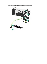
Page 32: ...3 15 Figure3 16 Connecting the grounding cable to a grounding strip 1 2 4 3 6 5 ...
Page 49: ...4 16 Figure4 16 Connecting an SFP DAC cable 1 Pull latch 2 Connector 1 2 ...
Page 92: ...A 12 FigureA 14 Example of a device label ...
Page 104: ...C 6 FigureC 5 Securing the chassis to the pallet base S12504G AF switch 1 1 2 2 1 ...


