
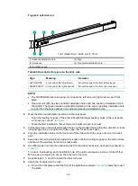
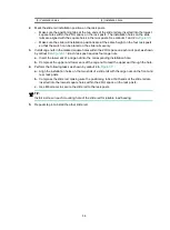
3-14
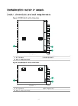
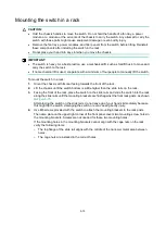
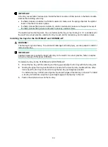
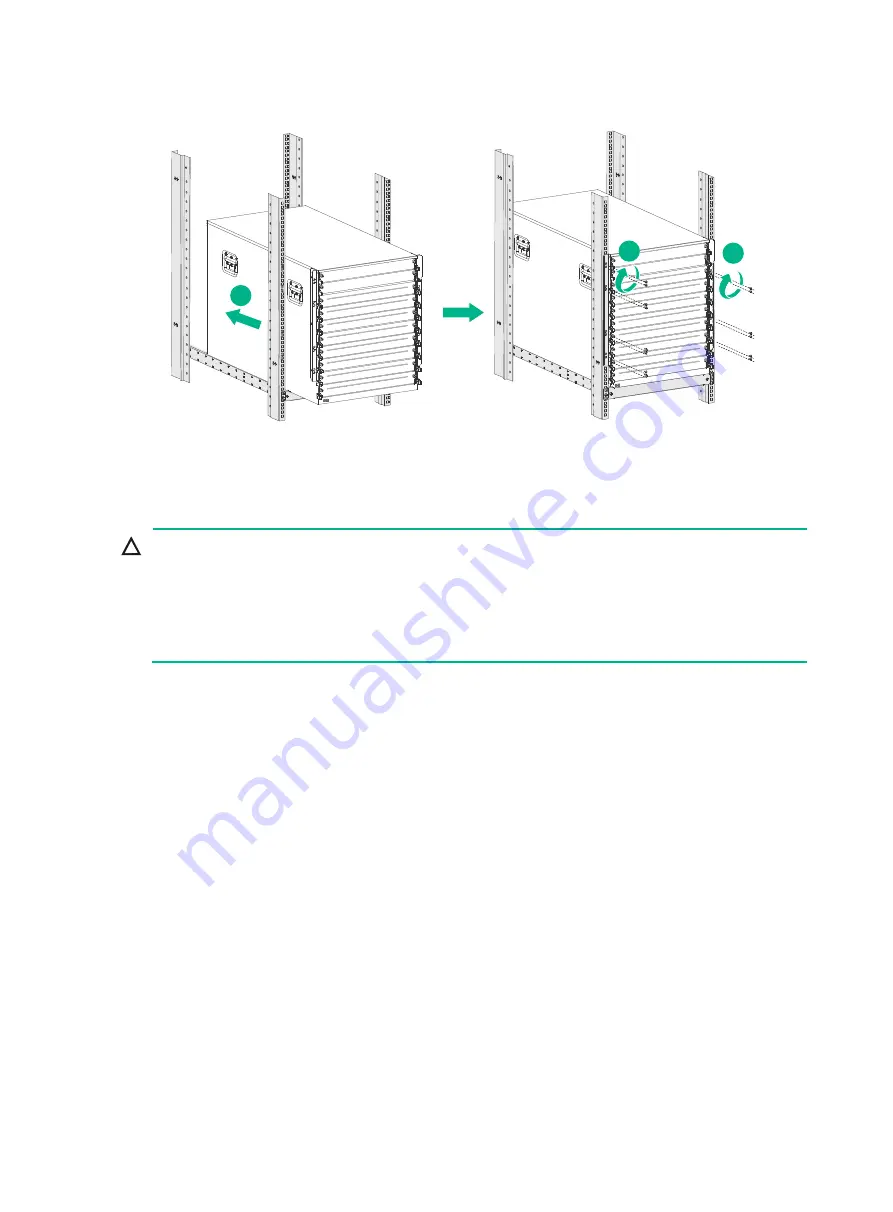
Figure3-15 Mounting the S12508G-AF switch in the rack
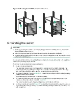
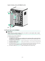
Grounding the switch
CAUTION:
•
Reliably grounding the switch is crucial to lightning protection and EMI protection. Ground the
switch reliably before you use it.
•
Use the grounding cable (yellow-green grounding cable) provided with the switch.
•
Connect the grounding cable to the earthing system in the equipment room. Do not connect it to
a fire main or lightning rod.
You can ground the switch by connecting the grounding cable to a grounding strip in the equipment
room or the grounding strip on the rack.
To connect the grounding cable to a grounding strip:
1.
Unpack the grounding cable.
The grounding cable provided with the switch is compliant with the NEBS standards. The
two-hole grounding lug of the grounding cable is used for connecting the chassis. The ring
terminal of the grounding cable is used for connecting the grounding strip.
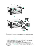
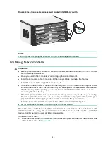
2.
As shown by callouts 1 and 2 in
, remove the grounding screws from the grounding
holes at the rear of the chassis.
A grounding sign is provided with the grounding holes.
3.
Use grounding screws to attach the two-hole grounding lug of the grounding cable to the
chassis, as shown by callouts 3 and 4 in
The recommended torque for the grounding screws is 30 kgf-cm (2.94 Nm).
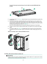
4.
As shown by callouts 5 and 6 in
, connect the ring terminal of the grounding cable to
a grounding post of the grounding strip, and fasten the grounding cable to the grounding strip
with the hex nut.
1
2
2
Summary of Contents for S12500G-AF Series
Page 32: ...3 15 Figure3 16 Connecting the grounding cable to a grounding strip 1 2 4 3 6 5 ...
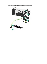
Page 49: ...4 16 Figure4 16 Connecting an SFP DAC cable 1 Pull latch 2 Connector 1 2 ...
Page 92: ...A 12 FigureA 14 Example of a device label ...
Page 104: ...C 6 FigureC 5 Securing the chassis to the pallet base S12504G AF switch 1 1 2 2 1 ...


