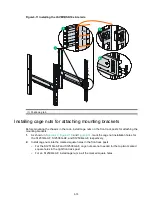


4-4
6.
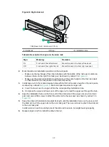
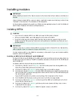
Fasten the captive screws on the MPU.
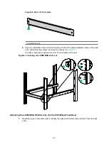
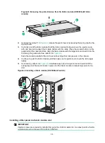
Figure4-3 Installing an MPU (S12504G-AF)
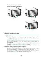
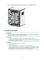
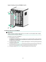
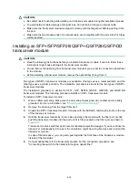
Installing service modules
CAUTION:
•
To prevent a filler panel from being drawn into the chassis when fan speed is high, use both
hands to grasp the filler panel by its two sides during filler panel installation and removal on an
operating switch.
•
Keep filler panels installed on unused service module slots.
The service module ejector levers and the ejector lever pillow blocks on the service module slots
have purple marks.
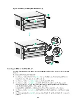
The installation procedure is similar for service modules and MPUs. For installing the service
modules, see "
Installing an MPU for the S12516G-AF and
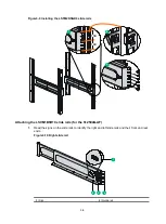
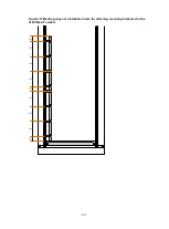
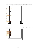
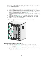
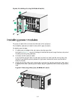
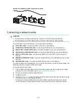
Installing cable management brackets
The cable management brackets are installed on the two sides of the service module slots. As a best
practice, install cable management brackets after you have installed service modules.
As shown in
, insert the cable management bracket end that has a spring tab into the cable
management bracket hole until the bracket has close contact with the hole.
1
2
3
4
5
6
Summary of Contents for S12500G-AF Series
Page 32: ...3 15 Figure3 16 Connecting the grounding cable to a grounding strip 1 2 4 3 6 5 ...
Page 49: ...4 16 Figure4 16 Connecting an SFP DAC cable 1 Pull latch 2 Connector 1 2 ...
Page 92: ...A 12 FigureA 14 Example of a device label ...
Page 104: ...C 6 FigureC 5 Securing the chassis to the pallet base S12504G AF switch 1 1 2 2 1 ...


