background image


2-4 

Gas 

Average concentration (mg/m

3

Maximum concentration (mg/m

3

O

3


0.05 

0.1 

NO

X


0.5 

1.0 


EMI 

All electromagnetic interference (EMI) sources, from outside or inside of the switch and application 
system, adversely affect the switch in the following ways: 


A conduction pattern of capacitance coupling. 


Inductance coupling. 


Electromagnetic wave radiation. 


Common impedance (including the grounding system) coupling. 

To prevent EMI, perform the following tasks: 


If AC power is used, use a single-phase three-wire power receptacle with protection earth (PE) 
to filter interference from the power grid. 


Keep the switch far away from radio transmitting stations, radar stations, and high-frequency 
devices. 


Use electromagnetic shielding, for example, shielded interface cables, when necessary. 

Grounding 

Correctly grounding the switch  is  crucial to lightning protection, anti-interference,  and ESD 
prevention.  Use  a good grounding system for the switch.  Make sure the resistance between the 
chassis and the ground is less than 1 ohm. 

For more information about grounding the switch, see "Grounding the switch." 

Power 

Perform the following tasks to meet the power requirements:  

1. 

Calculate the system power consumption. 

The system power consumption varies by module types and quantities. For more information 
about the system power consumption, see "Chassis views and technical specifications" in 

H3C 

S12500G-AF Switch Series Hardware Information and Specifications.


2. 

Identify the number of power modules based on the system power consumption. 

The total maximum output power of all power modules must be greater than the system power 
consumption. For more information about available power modules, see "FRUs and 
compatibility matrixes" in 

H3C S12500G-AF Switch Series Hardware Information and 

Specifications.


3. 

Verify that the power system at the installation site meets the requirements of the power 
modules, including the input method and rated input voltage. For more information about power 
module specifications, see "FRUs and compatibility matrixes" in 

H3C S12500G-AF Switch 

Series Hardware Information and Specifications.


Cooling 

Plan the installation site for adequate ventilation:  


Reserve a minimum clearance of 30 cm (11.81 in) around the inlet and outlet air vents. 

Summary of Contents for S12500G-AF Series

Page 1: ...H3C S12500G AF Switch Series Installation Guide New H3C Technologies Co Ltd http www h3c com Document version 6W102 20221025 ...

Page 2: ...r respective owners Notice The information in this document is subject to change without notice All contents in this document including statements information and recommendations are believed to be accurate but they are presented without warranty of any kind express or implied H3C shall not be liable for technical or editorial errors or omissions contained herein Environmental protection This prod...

Page 3: ...information describes the conventions used in the documentation Command conventions Convention Description Boldface Bold text represents commands and keywords that you enter literally as shown Italic Italic text represents arguments that you replace with actual values Square brackets enclose syntax choices keywords or arguments that are optional x y Braces enclose a set of required syntax choices ...

Page 4: ...nderstood or followed can result in data loss data corruption or damage to hardware or software IMPORTANT An alert that calls attention to essential information NOTE An alert that contains additional or supplementary information TIP An alert that provides helpful information Network topology icons Convention Description Represents a generic network device such as a router switch or firewall Repres...

Page 5: ... NetStream SSL VPN IPS or ACG module Examples provided in this document Examples in this document might use devices that differ from your device in hardware model configuration or software version It is normal that the port numbers sample output screenshots and other information in the examples differ from what you have on your device Documentation feedback You can e mail your comments about produ...

Page 6: ...i Contents 1 Installation precautions 1 1 Installing the switch 1 1 Installing a module 1 1 Installing a fan tray 1 1 Connecting the power cords 1 2 ...

Page 7: ...eliably before you use it Installing a module When you install a module avoid touching the connectors on it If you are not to install a module in a module slot install a filler panel in the slot A fan tray covers fabric module slots Install fabric modules or filler panels in the fabric module slots before installing a fan tray To replace or install a fabric module for an operating switch first rem...

Page 8: ...can hot swap a fan tray only when the other fan tray is operating correctly When you hot swap a fan tray the fan speed of the remaining fan trays automatically increases Take noise protection measures such as wearing an earmuff or earplug In addition make preparations before hot swapping a fan tray to minimize the operation time Connecting the power cords Power on the switch after you have install...

Page 9: ...ety recommendations 2 1 Electricity safety 2 1 Moving safety 2 1 ESD prevention 2 2 Laser safety 2 2 Examining the installation site 2 2 Weight support 2 2 Temperature 2 2 Humidity 2 3 Cleanliness 2 3 EMI 2 4 Grounding 2 4 Power 2 4 Cooling 2 4 Space 2 5 Installation accessories 2 5 ...

Page 10: ...lear the work area of possible electricity hazards such as ungrounded power extension cables missing safety grounds and wet floors Locate the emergency power off switch in the room before installation so you can quickly shut power off when an electrical accident occurs Remove all external cables including power cords before moving the chassis Do not work alone when the switch has power Before perf...

Page 11: ...switch make sure the installation site meets the following requirements Weight support Make sure the floor or ground at the installation site can support the combined weight of the switch and the rack The total weight of the switch includes the chassis and its components for example modules and power modules and accessories For the weights of the switch and its components see Chassis view and tech...

Page 12: ...t buildup on the chassis might result in electrostatic adsorption which causes poor contact of metal components and contact points In the worst case electrostatic adsorption can cause communication failure Table2 1 Dust concentration limits in the equipment room Substance Particle diameter Concentration limit Dust particles 0 5 µm 3 5 10 6 particles m 3 Dust particles 5 µm 3 10 4 particles m 3 Dus...

Page 13: ... information about grounding the switch see Grounding the switch Power Perform the following tasks to meet the power requirements 1 Calculate the system power consumption The system power consumption varies by module types and quantities For more information about the system power consumption see Chassis views and technical specifications in H3C S12500G AF Switch Series Hardware Information and Sp...

Page 14: ...ce follow these space requirements Reserve a minimum clearance of 1 2 m 3 94 ft between the rack and walls or other devices Make sure the rack has enough space to accommodate the switch For more information about switch dimensions and rack requirements see Switch dimensions and rack requirements Installation accessories Before installation make sure you have all the required installation accessori...

Page 15: ...service module filler panel S12516G AF 16 S12508G AF 8 S12504G AF 4 All S12500G AF models 2114A09Q S12500G AF power module filler panel S12516G AF 16 S12508G AF 8 S12504G AF 4 All S12500G AF models 2150A0AB S12500G AF cable management bracket S12516G AF 32 S12508G AF 16 S12504G AF 8 All S12500G AF models 26020141 26020075 M6 screw and cage nut S12516G AF 30 kits S12508G AF All S12500G AF models ...

Page 16: ...2500G AF models 28050001 ESD wrist strap 1 All S12500G AF models 04042967 Console cable 1 All S12500G AF models 0221A003 0221A004 Tweezers for installing and removing transceiver modules 1 set All S12500G AF models 14990101 SFP SFP dust plug Same number as the SFP SFP ports All S12500G AF service modules with SFP SFP ports 1499A00C QSFP dust plug Same number as the QSFP ports All S12500G AF servic...

Page 17: ...ation preparations 3 1 Installing the switch in a rack 3 2 Switch dimensions and rack requirements 3 2 Attaching slide rails to the rack 3 4 Installing cage nuts for attaching mounting brackets 3 10 Mounting the switch in a rack 3 13 Grounding the switch 3 14 ...

Page 18: ...ack is sturdy and reliably grounded No debris exists inside or around the rack The heaviest device is placed at the bottom of the rack The rack power supplying capabilities meet the device requirements For information about the system power consumptions module power consumptions and power module specifications see H3C S12500G AF Switch Series Hardware Information and Specifications The total heigh...

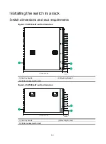
Page 19: ...igure3 1 S12516G AF switch dimensions 1 Fan tray handle 2 Mounting bracket 3 Cable management bracket Figure3 2 S12508G AF switch dimensions 1 Fan tray handle 2 Mounting bracket 3 Cable management bracket 1 2 3 102 mm 4 02 in 875 mm 34 45 in 1 2 3 102 mm 4 02 in 875 mm 34 45 in ...

Page 20: ...ay handles at the chassis rear A minimum of 1 1 m 3 61 ft in depth recommended A minimum of 130 mm 5 12 in between the front rack post and the front door A minimum of 950 mm 37 40 in between the front rack post and the rear door S12508G AF Total depth of 977 mm 38 46 in 102 mm 4 02 in from the rack facing surface of the mounting brackets to the front ends of the cable management brackets 875 mm 34...

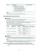
Page 21: ...e3 2 Switch weight and applicable slide rails Switch model Chassis weight full configuration Applicable slide rails Model Adjustment range Occupied space S12516G AF 360 kg 793 65 lb LSXM1BSR 630 to 900 mm 24 80 to 35 43 in 1 RU S12508G AF 200 kg 440 92 lb LSXM1BSR 630 to 900 mm 24 80 to 35 43 in 1 RU LSTM2KSGD0 500 to 800 mm 19 69 to 31 50 in 2 RU S12504G AF 115 kg 253 53 lb LSVM1BSR10 630 to 850 ...

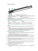
Page 22: ...ry holes in the rack posts as shown by callout 1 in Figure3 7 Mark the start installation hole at the same height on each rack post 3 Install cage nuts in the marked standard hole and the standard hole within the same RU A total of eight cage nuts are required with two cage nuts for each rack post 4 Align the installation holes on the front end of the slide rail with the cage nuts on a front rack ...

Page 23: ...de rails and fasten the screws as shown by callout 3 in Figure3 7 Two M4 screws are required to secure the front plate to the rack Figure3 7 Installing the LSXM1BSR slide rails Attaching the LSTM2KSGD0 slide rails for the S12508G AF switches 1 Read the signs on the slide rails to identify the right and left slide rails and their front and rear ends 1 1 2 3 ...

Page 24: ...square holes within 2 RU at the same height on the rack posts as shown by callout 2 in Figure3 9 Each rack post requires six cage nuts a Insert the lower ear of a cage nut into the corresponding installation hole b Compress the upper and lower ears of the cage nut to lead the upper ear through the hole 4 Align the installation holes on the front end of the slide rail with the cage nuts on a front ...

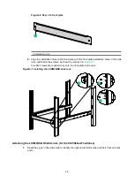
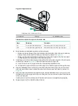
Page 25: ...ls Attaching the LSVM1BSR10 slide rails for the S12504G AF 1 Read the signs on the slide rails to identify the right and left slide rails and their front and rear ends Figure3 10 Right slide rail 1 Sign 2 Guide rail 1 2 1RU 1RU 3 1 2 3 1 2 3 4 1 2 3 4 ...

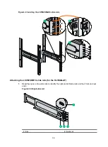
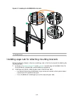
Page 26: ...n each rack post as shown by callout 3 in Figure3 11 Each rack post requires four cage nuts a Insert the lower ear of a cage nut into the corresponding installation hole b Compress the upper and lower ears of the cage nut to lead the upper ear through the hole 4 Perform the following tasks as shown by callout 4 in Figure3 11 a Align the installation holes on the two ends of a slide rail with the c...

Page 27: ...ackets 1 As shown in Figure3 12 Figure3 13 and Figure3 14 mark the cage nut installation holes for the S12516G AF S12508G AF and S12504G AF respectively 2 Install cage nuts into the marked square holes in the front rack posts For the S12516G AF and S12508G AF cage nuts are not needed for the top two marked square holes in the right front rack post For an S12504G AF install cage nuts in all the mar...

Page 28: ...3 11 Figure3 12 Marking cage nut installation holes for attaching mounting brackets for the S12516G AF switch 1RU 3RU 3RU 3RU 1RU 3RU 3RU 3RU 1RU ...

Page 29: ...cage nut installation holes for attaching mounting brackets for the S12508G AF switch Figure3 14 Marking cage nut installation holes for attaching mounting brackets for the S12504G AF switch 1RU 2RU 4RU 2RU 1RU 2RU 1U 1U 1U 1U ...

Page 30: ...rds the front of the rack 2 Lift the chassis until the switch bottom is a little higher than the slide rails on the rack 3 Facing the front of the rack place the switch on the slide rails and slide the switch into the rack along the slide rails until the mounting brackets are flush against the front rack posts as shown in Figure3 15 After placing the switch on the slide rails do not leave go of yo...

Page 31: ...unding cable provided with the switch is compliant with the NEBS standards The two hole grounding lug of the grounding cable is used for connecting the chassis The ring terminal of the grounding cable is used for connecting the grounding strip 2 As shown by callouts 1 and 2 in Figure3 16 remove the grounding screws from the grounding holes at the rear of the chassis A grounding sign is provided wi...

Page 32: ...3 15 Figure3 16 Connecting the grounding cable to a grounding strip 1 2 4 3 6 5 ...

Page 33: ...nagement brackets 4 4 Installing fabric modules 4 5 Installing fan trays 4 8 Installing power modules 4 11 Connecting the power cord 4 12 Connecting an AC power cord 4 12 Connecting a DC power cord 4 13 Installing transceiver modules and optical fibers 4 13 Installing an SFP SFP SFP28 QSFP QSFP28 QSFP DD transceiver module 4 14 Connecting a network cable 4 15 ...

Page 34: ...es for future use Attaching an ESD wrist strap The switch is provided with an ESD wrist strap To minimize ESD damage to electronic components wear the ESD wrist strap and make sure it is reliably grounded before you install FRUs To attach an ESD wrist strap 1 Make sure the switch is reliably grounded For information about how to ground your switch see Grounding the switch 2 Put on the wrist strap ...

Page 35: ...install it in either of the MPU slots Installing an MPU for the S12516G AF and S12508G AF For the S12516G AF and S12508G AF the MPU ejector levers and the ejector lever pillow blocks on the MPU slots are pink marked The MPU installation procedure is the same for the S12516G AF and S12508G AF To install an MPU for the S12516G AF and S12508G AF 1 As shown by callouts 1 and 2 in Figure4 2 remove the ...

Page 36: ...t 3 in Figure4 3 pivot up the handle of the MPU 3 As shown by callout 4 in Figure4 3 orient the MPU with the lettering on it facing upward Holding the MPU by the front panel with one hand and supporting the bottom with the other push the MPU steadily into the slot along the guide rails Keep the MPU parallel to the slot to avoid touching other components in the chassis 4 As shown by callout 5 in Fi...

Page 37: ...ctor lever pillow blocks on the service module slots have purple marks The installation procedure is similar for service modules and MPUs For installing the service modules see Installing an MPU for the S12516G AF and S12508G AF Installing cable management brackets The cable management brackets are installed on the two sides of the service module slots As a best practice install cable management b...

Page 38: ... starts operating you can replace or install fabric modules whose slots are covered by the other fan tray The smart speed adjustment feature increases the fan speed when only one fan tray is operating Take noise protection measures such as wearing an earmuff or earplug In addition make good preparation before hot swapping a fabric module to minimize the operation time Install fabric modules from t...

Page 39: ... guide rails See callout 2 in Figure4 6 Keep the module parallel to the slot to avoid touching other components in the chassis 4 Continue to push the fabric module until the brakes on its ejector levers touch the slot edges tightly 5 As shown by callout 3 in Figure4 6 simultaneously rotate the ejector levers inward until the spring clips lock the ejector levers in place and the fabric module is co...

Page 40: ...ler panel parallel to the fabric module slot to avoid touching other components in the chassis 3 As shown by callout 2 in Figure4 7 continue to push the filler panel until the brakes on its ejector levers touch the slot edges tightly Simultaneously rotate the ejector levers inward 4 Fasten the captive screws on the ejector levers Figure4 7 Installing a filler panel in a fabric module slot S12508G ...

Page 41: ...t dust from entering the chassis make sure each fan tray slot has a filler panel or fan tray installed when the switch is not in use CAUTION When you hot swap fan trays follow these guidelines Ensure electricity safety You can hot swap a fan tray only when the other fan tray is operating correctly When you hot swap a fan tray the fan speed of the remaining fan trays automatically increases Take no...

Page 42: ...ays for the S12516G AF and S12508G AF WARNING The fan tray is high and heavy To avoid switch damage and bodily injury use two people to install or remove a fan tray IMPORTANT Captive screws are required to install a fan tray on the switch As a best practice fasten a captive screw to a torque of 5 5 kgf cm 0 54 Nm To install a fan tray for the S12516G AF and S12508G AF 1 Orient the fan tray with th...

Page 43: ...o that the LEDs are on the left side of the front panel To install a fan tray in the FAN2 slot orient the fan tray so that the LEDs are on the right side of the front panel 2 As shown by callout 1 in Figure4 10 align the positioning pin on the fan tray with the positioning hole above the fan tray slot 3 As shown by callout 2 in Figure4 10 hold the fan tray handle and insert the fan tray into the s...

Page 44: ...r panel through the hole and pull out the filler panel along the guide rails 2 Correctly orient the power module If you install the power module in a left power module slot make sure the latch is above the handle If you install the power module in a right power module slot make sure the latch is below the handle 3 Holding the handle of the power module with one hand and supporting the bottom of th...

Page 45: ...rcuit breaker Turn off the circuit breaker before you connect the power cord Connecting an AC power cord 1 Connect the AC power cord connector to the AC input receptacle of the power module 2 Use a removable cable tie or self adhesive cable tie provided with the power module to secure the power cord to the handle of the power module 3 Connect the other end of the power cord to an external AC power...

Page 46: ...e connector to secure the connector to the receptacle 3 Connect the other end of the power cord to an external DC power source Figure4 14 Connecting the DC power cord S12508G AF switch Installing transceiver modules and optical fibers WARNING Disconnected optical fibers or transceiver modules might emit invisible laser light Do not stare into beams or view directly with optical instruments when th...

Page 47: ...of QSFP transceiver modules The installation procedure is similar for SFP SFP SFP28 QSFP QSFP28 and QSFP DD transceiver modules The following procedure installs an SFP transceiver module To install an SFP transceiver module 1 Wear an ESD wrist strap Make sure the wrist strap makes good skin contact and is reliably grounded For more information see Attaching an ESD wrist strap 2 Remove the dust plu...

Page 48: ...tance QSFP28 to SFP28 DAC cable Connects one QSFP28 port to four SFP28 ports over a short distance QSFP DD DAC cable Connects two QSFP DD ports over a short distance The network cables are hot swappable The connection procedure is similar for these cables The following procedure connects an SFP DAC cable To connect an SFP DAC cable 1 Wear an ESD wrist strap Make sure the wrist strap makes good ski...

Page 49: ...4 16 Figure4 16 Connecting an SFP DAC cable 1 Pull latch 2 Connector 1 2 ...

Page 50: ...e installation site 5 2 Identifying the master switch and planning IRF member IDs 5 2 Planning IRF topology and connections 5 3 Identifying physical IRF ports on the member switches 5 3 Installing IRF member switches 5 3 Configuring basic IRF settings 5 3 Connecting the physical IRF ports 5 4 Verifying the IRF fabric configuration 5 4 ...

Page 51: ...IRF Configuration Guide for the software release you are using Figure5 1 IRF fabric setup flowchart To set up an IRF fabric Step Description 1 Plan IRF fabric setup Plan the installation site and IRF fabric setup parameters Planning IRF fabric size and the installation site Identifying the master switch and planning IRF member IDs Planning IRF topology and connections Start Plan IRF fabric setup I...

Page 52: ...r switches must be the same model 3 Select modules that can provide 10 GE 25 GE 40 GE 100 GE 400 GE ports The S12500G AF switch series requires 10 GE 25 GE 40 GE 100 GE 400 GE ports for IRF connection For more information about the modules see H3C S12500G AF Switch Series Hardware Information and Specifications 4 Select SFP SFP28 QSFP QSFP28 QSFP DD transceiver modules and fibers for long distance...

Page 53: ... ports You can bind up to eight physical ports to one IRF port Installing IRF member switches Step Reference 1 Prepare the installation site See Preparing for installation 2 Mount the IRF member switches to racks See Installing the switch 3 Install modules on IRF member switches See Installing FRUs Configuring basic IRF settings After you install the IRF member switches power on the switches and l...

Page 54: ...smission When connecting SFP ports connect the transmit port of the SFP transceiver module at one end to the receive port of the SFP transceiver module at the other end The transceiver modules at the two ends of an IRF link must be the same type For more information about installing transceiver modules see Installing an SFP SFP SFP28 QSFP QSFP28 QSFP DD transceiver module For more information abou...

Page 55: ... about the IRF fabric display irf configuration Display topology information about the IRF fabric display irf topology To avoid IP address collision and network problems configure a minimum of one MAD mechanism to detect the presence of multiple identical IRF fabrics and handle collisions For more information about MAD see H3C S12500G AF Switch Series IRF Configuration Guide ...

Page 56: ...6 2 Configuring the switch 6 3 Configuring authentication on a user interface 6 4 Configuring the basic access function 6 4 Configuration example 6 4 Verifying the network configuration 6 5 Connecting the switch to the network 6 6 Connecting the switch to the network by using Ethernet twisted pair cables 6 6 Connecting the switch to the network through an optical fiber 6 6 Testing connectivity 6 7...

Page 57: ... an IRF fabric supports equals the number of MPUs in the IRF fabric The switch supports a maximum of 64 concurrent VTY users Accessing the switch for the first time The first time you access the switch you must use a console cable to connect a console terminal for example a PC to the console port on the switch Setting up the configuration environment To connect a terminal for example a PC to the s...

Page 58: ...ing on the switch Before powering on the switch confirm the following You know where the emergency power off switch for the equipment room is located The switch has been securely mounted All the modules have been correctly installed The unused slots have been installed with filler panels All the network cables fibers power cords and grounding cables have been correctly connected The input power vo...

Page 59: ...e Image file flash s12500g cmw710 boot e7593 bin is self decompressing Done System image is starting Line aux0 is available Press ENTER to get started Press Enter sysname The switch is ready for configuration After powering on the switch check the following items The cooling system is working and you can hear fan rotating noise and feel air being blown out The system status LEDs on the MPUs show t...

Page 60: ...es Fundamentals Configuration Guide Configuring the basic access function The switch without any configuration can perform basic data forwarding immediately after it is connected to a network To implement more forwarding features configure the basic network settings in Table6 2 on the switch Table6 2 Basic network settings Setting Description IP address Enables remote switch management for example...

Page 61: ...0 quit Configure MSTP Create an MST region named example map VLAN 10 to instance 1 and set the MSTP revision level to 0 Sysname stp region configuration Sysname mst region region name example Sysname mst region instance 1 vlan 10 Sysname mst region revision level 0 Activate the MST region configuration Sysname mst region active region configuration Sysname mst region quit Configure the switch as t...

Page 62: ...n H3C S12500G AF Switch Series Hardware Information and Specifications To connect a copper port to a peer device through an Ethernet twisted pair cable 1 Plug one end of the cable into the RJ 45 port on the switch 2 Plug the other end of the cable to the RJ 45 port of the peer device 3 Verify that the RJ 45 ports are operating correctly by examining the LED status For more information about the LE...

Page 63: ...ceiver module 4 Examine the port LEDs for incorrect connection For more information about the LED status see H3C S12500G AF Switch Series Hardware Information and Specifications NOTE For the QSFP QSFP28 transceiver module you do not need to differentiate between the transmitter TX and receiver RX ports For other types of transceiver modules the TX port on one end must connect to the RX port on the...

Page 64: ... startup 7 1 No display on the configuration terminal 7 1 Garbled display on the configuration terminal 7 2 System failures during operation 7 2 Power module failure 7 2 Fan tray failure 7 3 MPU failure 7 4 Service module failure 7 4 Fabric module failure 7 5 Interface failure 7 6 Technical support 7 7 ...

Page 65: ...odules provide port status LEDs with which you can detect port failures For more information about port status LEDs see H3C S12500G AF Switch Series Hardware Information and Specifications If you cannot locate failures by following the guidelines in this chapter contact the local agents or technical support engineers For more information see Technical support Configuration terminal display issues ...

Page 66: ...on error is found re configure the switch or restore the factory default settings For more information see H3C S12500G AF Switch Series Fundamentals Configuration Guide 3 If the issue persists contact H3C Support Power module failure Symptom The LEDs for the power module are in the following states On the MPU the power module LED is steady red The power module LED is steady green only when all the...

Page 67: ...ame model in the same slot and connect it to the same power source If the new power module can operate correctly the old power module has failed Contact your sales agent or local service engineer to replace the old power module 10 If the issue persists contact H3C Support Fan tray failure Symptom The LEDs for the fan tray are in the following states On the MPU the fan tray LED is steady red On the...

Page 68: ...ot number is marked on the ejector lever pillow blocks at the left and right sides of the slot You can see the fabric module slot numbers through the openings in the fan trays as shown by callout 3 in the Figure7 2 Service module failure Symptom The LED for the service module is steady red or flashing red Solution To resolve the issue 1 Verify that the MPU is operating correctly For more informati...

Page 69: ...d S12508G AF fan trays the RUN and ALM LED pairs correspond to the fabric module slots from left to right See Figure7 1 On the S12504G AF fan tray the extended lines of the RUN and ALM LED pairs correspond to the fabric module slots from left to right Figure7 1 Corresponding relations between the LEDs on the S12508G AF fan trays and fabric module slots 1 LEDs for the fabric module slots 10 11 and ...

Page 70: ...ric module 3 Calculate the total power consumption and make sure your power modules can provide enough power For more information see H3C S12500G AF Switch Series Hardware Information and Specifications 4 Remove and reinstall the fabric module to make sure the module is installed securely You also need to verify that the ejector levers are locked securely in place For more information see Installi...

Page 71: ...s compatible with the transceiver and that the transceiver is compatible with the cable For more information see H3C S12500G AF Switch Series Hardware Information and Specifications b Replace the transceiver module 5 Verify that the speed and duplex settings of the interfaces on the two ends are the same 6 If the issue persists contact H3C Support NOTE If an interface is brought down by the shutdo...

Page 72: ... Replacing a module 8 2 Replacing an MPU or service module 8 2 Replacing a fabric module 8 4 Replacing a fan tray 8 5 Replacing a transceiver module or network cable 8 6 Replacing an SFP SFP SFP28 QSFP QSFP28 QSFP DD transceiver module 8 6 Replacing a network cable 8 7 ...

Page 73: ...ore replacing a power module turn off its circuit breaker The power module might be of high temperature Remove it with caution To install the removed power module in the chassis again install it after the status LED on it is off Strictly follow the procedures shown in Figure8 1 and Figure8 2 to replace a power module to avoid device damage and bodily injury Figure8 1 Power module removal procedure...

Page 74: ...g tasks MPU or service module Loosen the captive screws on the module Fabric module Press the spring clips for the ejector levers to release them If you are not to install a module in a slot install a blank filler panel in the slot to ensure adequate ventilation and dust prevention Replacing an MPU or service module Replacing a service module S12516G AF MPU or S12508G AF MPU The replacement proced...

Page 75: ...an antistatic mat to place the removed MPU 2 Wear an ESD wrist strap and make sure it makes good skin contact and is reliably grounded For more information see Attaching an ESD wrist strap 3 Use a Phillips screwdriver to loosen the captive screws on the MPU as shown by callout 1 in Figure8 5 4 As shown by callout 2 in Figure8 5 pivot up the handle of the MPU to disengage the MPU from the slot 5 As...

Page 76: ...rays at the same time Remove one fan tray to replace or install fabric modules in the slots covered by the fan tray and then reinstall the fan tray You can remove the other fan tray only after this fan tray operates correctly To replace a fabric module 1 Prepare an antistatic mat to place the removed fabric module 2 Wear an ESD wrist strap and make sure it makes good skin contact and is reliably g...

Page 77: ...in the chassis until a new fan tray is ready to be installed Before hot swapping a fan tray make sure the other fan tray is operating correctly To replace a fan tray 1 Prepare an antistatic mat to place the fan tray to be removed 2 Put on an ESD wrist strap and make sure the wrist strap makes good skin contact and is reliably grounded For more information see Attaching an ESD wrist strap 3 Loosen ...

Page 78: ...SFP QSFP28 QSFP DD transceiver module WARNING Disconnected optical fibers or transceiver modules might emit invisible laser light Do not stare into beams or view directly with optical instruments when the switch is operating CAUTION Be careful not to touch the golden plating on a transceiver module during the removal process To replace an SFP SFP SFP28 QSFP QSFP28 QSFP DD transceiver module 1 Wear...

Page 79: ...rt to prevent particles from entering the port Replacing a network cable CAUTION If the cable cannot be removed or installed verify that the removal or installation procedures are correct Pull the pull latch horizontally for smooth removal and avoiding damage If you are not to install a new network cable in the port insert the dust plug that is provided with the module into the port to prevent par...

Page 80: ...ixing labels A 3 Affixing a label to a network cable A 3 Affixing a label to a power cord A 4 Affixing a generic label A 5 Affixing a label to a device A 6 Guidelines A 6 Examples A 6 Engineering labels for twisted pair cables A 6 Engineering labels for optical fibers A 7 Engineering labels for DC power cords A 9 Engineering labels for AC power cords A 10 Engineering labels for devices A 11 ...

Page 81: ...ify the peer end of the cable on which the label is affixed As shown in FigureA 1 write a network cable label as follows Write the position of the cable in Area 1 Write the position of the cable on the peer end in Area 2 Area 3 is the part that is folded up inside the label when the label is affixed to the cable FigureA 1 Label for network cables 1 Dividing line 2 Cut dotted line Labels for power ...

Page 82: ...c label is bar shaped with fixed dimensions It is applicable to all cables A mark TO is located at the upper left corner in the right area of the label to identify the peer end of the cable on which the label is affixed The meaning of the dividing lines is the same as labels for network cables TO 1 2 ...

Page 83: ... about using a label printer see the user guide of the printer To write labels use black markers A marker has two nibs Be sure to use the smaller nib to write labels Affixing labels After printing or writing a label remove the label from the bottom page and affix it to the network cable or the identification plate of the power cord Affixing a label to a network cable Typically a label is affixed 2...

Page 84: ...area on the identification plate You can stick the label to either side of the identification plate Be sure to affix the labels on the same side of the identification plates A cable tie is bundled 2 cm 0 79 in away from the connector You can affix the label to other positions as needed FigureA 6 shows how to affix a label when a cable is laid horizontally Adhesive side TO B02 03 12 1 2 3 4 5 TO B0...

Page 85: ...ht side of the cable in vertical cabling Make sure the label is facing out as shown in FigureA 7 FigureA 7 Affixed labels Affixing a generic label The requirements for affixing a generic label are the same as affixing a label on a network cable For more information see Affixing a label to a network cable For the example of affixed labels see FigureA 8 TO B03 48V2 TO B03 48V2 TO B03 48V2 ...

Page 86: ... cords with identification plates on the same side The positions of up down right or left are all based on the viewpoint of the engineering person who is working on the label Examples The label examples in this document are for reference only Engineering labels for twisted pair cables These labels are affixed to twisted pair cables that connect cards in a chassis TableA 1 Information on a label af...

Page 87: ...or the specific location of the server if the server is laid separately On a label for the twisted pair cable that connects the switch and a terminal For the switch end Rack number chassis number and Ethernet port number or the specific location of the switch if the switch is laid separately The definitions of the rack number and chassis number are the same as those described in TableA 1 For the t...

Page 88: ...mber D Fiber port number R Optical receiving interface T Optical transmitting interface N A Labels for the fiber that connects the device and the ODF TableA 3 Information on labels affixed to the fiber between the device and the ODF Content Meaning Example MN B C D R T MN Rack number M Row number of the rack in the equipment room in the range of A to Z N Column number of the rack in the equipment ...

Page 89: ...lumn 01 in the equipment room FigureA 11 Example of a label on an optical fiber between the device and the ODF ODF G01 01 01 R The local end of the optical fiber is connected to the optical receiving terminal on Row 01 Column 01 of the ODF in Row G Column 01 in the equipment room A01 01 05 05 R The peer end of the optical fiber is connected to Optical Receiving Interface 5 on Slot 05 Chassis 01 in...

Page 90: ...m the 8 th connector on the second row of 48V bus bar in the cabinet on Row A and Column 1 in the equipment room B03 48V2 distribution box side The power cord is 48V2 DC supply which is from the loaded cabinet on Row B Column 03 in the equipment room In the power distribution box or the first power cabinet of a row in the transmission equipment room every terminal block on the 48V connector bar ha...

Page 91: ... about the local end is not necessary Make sure labels are affixed in the correct direction After the cable ties are bundled onto the cable the identification plates with the labels must face up and the text on the labels in the same cabinet must be in the same direction as shown in FigureA 13 FigureA 13 Example of labels on an AC power cord A01 AC loaded cabinet side The power cord is connected t...

Page 92: ...A 12 FigureA 14 Example of a device label ...

Page 93: ...i Contents Appendix B Cabling recommendations B 1 Routing signal cables B 1 Routing power cords B 1 General cabling requirements B 1 Prerequisites B 2 Cable management guidelines B 2 ...

Page 94: ...o not place them at a location out of the rack and easy to reach The power modules are located at the left and right of the rear panel As a best practice route power cords from the left and right of the rear panel General cabling requirements Minimum curvature radius of cables Attached power cord communication cable or ribbon cable A minimum of five times the cable s outer diameter If the cable is...

Page 95: ... them Cable management guidelines When you route and bundle up cables follow these guidelines Bind and route the cables neatly inside the rack and make sure they are not kinked or bent FigureB 2 Correct and incorrect cable binding The cable bend radius at connectors must be a minimum of 5 times the cable diameter and must be a minimum of twice the cable diameter away from the connectors Route diff...

Page 96: ...core break do not tie up the cables in the bending area FigureB 4 Binding cables where they must be bent Route bind and attach excess cables for easy safe maintenance activities and correct operations Do not tie power cords to slide rails When you connect a cable to an articulated part for example when you connect a grounding cable to a cabinet door leave enough slack in cables and make sure they ...

Page 97: ... Bind together cables that are the same type and routed in the same direction TableB 1 lists the cable bundling specifications TableB 1 Tie binding parameters Cable bundle diameter mm Space between bundles mm 10 80 to 150 10 to 30 150 to 200 30 200 to 300 Do not tie cables or bundles in a knot The metal parts of the crimped cold pressed terminal blocks such as air switch cannot protrude beyond the...

Page 98: ...e cable C 1 Removing the grounding cable C 1 Removing the twisted pair cables and optical fibers C 2 Repacking the FRUs C 2 Repacking power modules C 2 Repacking the modules C 3 Repacking the fabric module slot filler panels C 3 Repacking the switch chassis C 3 Removing the chassis from the rack C 3 Repacking the switch chassis C 4 ...

Page 99: ...e For a DC power cord loosen the screws on the power cord connector and then remove the connector from the power module 4 Perform the same step to remove the other power cords Removing the console cable 1 Pull the RJ 45 connector of the console cable out from the console port of the switch 2 Pull the DB 9 connector of the console cable out from the serial port of the PC or the terminal Removing th...

Page 100: ...e input ends of all power cords and remove all the power cords to avoid device damage and bodily injury To repack power modules 1 Prepare the original packing materials including the anti static bag foam cushion and packing box for a power module Make sure these packing materials are clean dry and not damaged 2 Remove the power module from the chassis For more information see Replacing a power mod...

Page 101: ...ut the module and the foam cushion into the box and seal the box with tape 7 Perform the same steps to repack the other modules NOTE The switch comes with a filler panel in all slots except the fabric module slots Repacking the fabric module slot filler panels 1 Prepare the original packing materials including the packing bag foam cushion and packing box for a fabric module slot filler panel Make ...

Page 102: ...he rack 5 Put the chassis onto the wooden pallet base FigureC 2 Removing the switch from the rack S12508G AF switch Repacking the switch chassis 1 Align the left and right edges of the chassis bottom with the left and right positioning lines respectively on the wooden pallet base See FigureC 3 for the wooden pallet base FigureC 3 Wooden pallet base 1 Wooden pallet base 2 Left positioning line 3 Ri...

Page 103: ...5 Place the foam cushion onto the chassis top and make sure the mounting brackets seat into the internal notches of the foam cushion See callout 2 of FigureC 6 6 Fit the accessory box into the rear notch of the foam cushion as shown in callout 3 of FigureC 6 7 Erect one paper corner protector along each vertical edge of the chassis and use the carton to cover the chassis from top down with the mar...

Page 104: ...C 6 FigureC 5 Securing the chassis to the pallet base S12504G AF switch 1 1 2 2 1 ...

Page 105: ...C 7 FigureC 6 Locating the foam cushion and the accessory box 1 Chassis front panel side 2 Seat the mounting brackets into the internal notches of the foam cushion 3 Accessory box 1 2 3 ...

Reviews: