

8-1
8
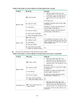
Replacement procedures
CAUTION:
•
When replacing FRUs while the switch is operating, ensure electrical safety.
•
To avoid bodily injury and device damage, follow the replacement procedures strictly.
•
Long-time exposure to strong air flow might cause discomfort. To avoid this hazard, do not stand
close to the air outlet vents while the switch is operating. If you must be next to the switch on the
air outlet vent side for an extended period, avoid the air flow or take other protective measures.
•
As a best practice to avoid data theft, remove all data from an FRU that has a storage medium,
for example, a disk or flash before disposal of that FRU. To remove data, format or destroy the
storage medium on the FRU.
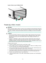
The switch uses a modular, hot-swappable architecture, and supports FRUs. You can replace the
FRUs when the switch is operating.
Replacing a power module
CAUTION:
•
Provide a circuit breaker for each power module. Before replacing a power module, turn off its
circuit breaker.
•
The power module might be of high temperature. Remove it with caution.
•
To install the removed power module in the chassis again, install it after the status LED on it is off.
Strictly follow the procedures shown in
to replace a power module to avoid
device damage and bodily injury.
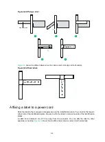
Figure8-1 Power module removal procedure
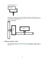
Figure8-2 Power module installation procedure
To replace a power module:
1.
Prepare an antistatic mat to place the removed power module.
2.
Turn off the circuit breaker.
3.
Wear an ESD wrist strap, and make sure it makes good skin contact and is reliably grounded.
For more information, see "Attaching an ESD wrist strap."
4.
Remove the power cord.
For an AC power module, remove the cable tie, and then remove the power cord connector
from the power module.
For a DC power module, loosen the screw on the power cord connector, and then remove
the connector from the power module.
Turn off the circuit
breaker
Remove the power
cord
Remove the power
module
Install the power
module
Connect the power
cord
Turn on the circuit
breaker
Summary of Contents for S12500G-AF Series
Page 32: ...3 15 Figure3 16 Connecting the grounding cable to a grounding strip 1 2 4 3 6 5 ...
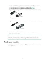
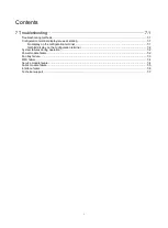
Page 49: ...4 16 Figure4 16 Connecting an SFP DAC cable 1 Pull latch 2 Connector 1 2 ...
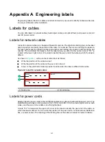
Page 92: ...A 12 FigureA 14 Example of a device label ...
Page 104: ...C 6 FigureC 5 Securing the chassis to the pallet base S12504G AF switch 1 1 2 2 1 ...


