


3-3
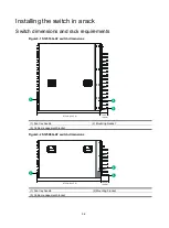
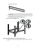
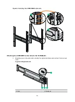
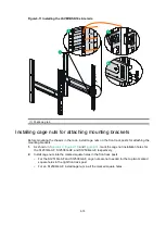
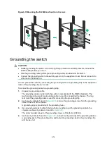
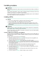
Figure3-3 S12504G-AF dimensions (with the LSXM104XFAN fan trays)
(1) Fan tray handle
(2) Mounting bracket
(3) Cable management bracket
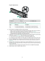
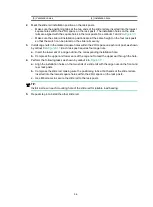
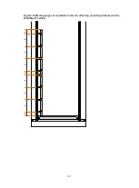
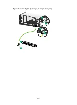
Figure3-4 S12504G-AF dimensions (with the LSXM104XFANH fan trays)
(1) Fan tray handle
(2) Mounting bracket
(3) Cable management bracket
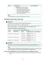
To mount the switch in an enclosed rack, make sure the rack meets the requirements described in
Table3-1 Switch dimensions and rack requirements
Model
Chassis depth
Rack requirements
S12516G-AF
Total depth of 977 mm (38.46 in)
•
102 mm (4.02 in) from the rack-facing surface of
the mounting brackets to the front ends of the
cable management brackets
•
875 mm (34.45 in) from the rack-facing surface
of the mounting brackets to the fan tray handles
at the chassis rear
•
A minimum of 1.1 m (3.61 ft)
in depth (recommended)
•
A minimum of 130 mm (5.12
in) between the front rack
post and the front door.
•
A minimum of 950 mm
(37.40 in) between the front
rack post and the rear door.
S12508G-AF
Total depth of 977 mm (38.46 in)
•
102 mm (4.02 in) from the rack-facing surface of
the mounting brackets to the front ends of the
cable management brackets
•
875 mm (34.45 in) from the rack-facing surface
of the mounting brackets to the fan tray handles
at the chassis rear
S12504G-AF
•
Total depth
—977 mm (38.46 in) when the
LSXM104XFAN fan trays are installed:
102 mm (4.02 in) from the rack-facing
surface of the mounting brackets to the front
ends of the cable management brackets
875 mm (34.45 in) from the rack-facing
surface of the mounting brackets to the fan
tray handles at the chassis rear
1
2
3
102 mm
(4.02 in)
875 mm (34.45 in)
1
2
3
102 mm
(4.02 in)
914 mm (35.98 in)
Summary of Contents for S12500G-AF Series
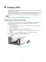
Page 32: ...3 15 Figure3 16 Connecting the grounding cable to a grounding strip 1 2 4 3 6 5 ...
Page 49: ...4 16 Figure4 16 Connecting an SFP DAC cable 1 Pull latch 2 Connector 1 2 ...
Page 92: ...A 12 FigureA 14 Example of a device label ...
Page 104: ...C 6 FigureC 5 Securing the chassis to the pallet base S12504G AF switch 1 1 2 2 1 ...


