

8-4
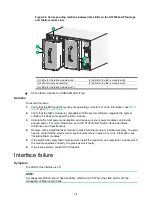
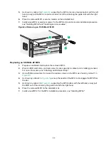
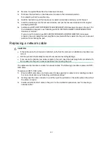
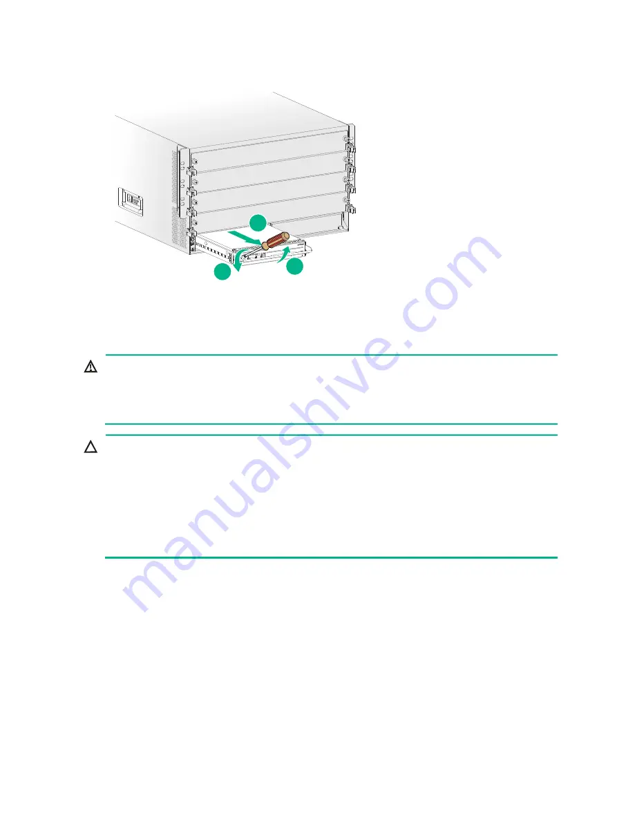
Figure8-5 Removing an S12504G-AF MPU
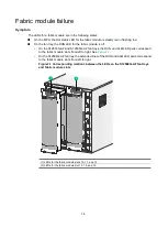
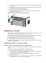
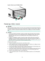
Replacing a fabric module
WARNING!
When you hot swap a fabric module, only one fan tray is operating and it automatically increases the
fan rotation speed and makes louder noise. Take protection measures such as wearing an earmuff
or earplug. In addition, make good preparation before the hot swapping to minimize the operation
time.
CAUTION:
•
Fan trays cover fabric module slots. To remove a fabric module, first remove the fan tray that
covers the fabric module. For more information about the relationship between fabric module
slots and fan tray slots, see
H3C S12500G-AF Switch Series Hardware Information and
Specifications
.
•
To replace or install fabric modules in the slots covered by both fan trays when the switch is
operating, do not remove both fan trays at the same time. Remove one fan tray to replace or
install fabric modules in the slots covered by the fan tray, and then reinstall the fan tray. You can
remove the other fan tray only after this fan tray operates correctly.
To replace a fabric module:
1.
Prepare an antistatic mat to place the removed fabric module.
2.
Wear an ESD wrist strap, and make sure it makes good skin contact and is reliably grounded.
For more information, see "Attaching an ESD wrist strap."
3.
Press the spring clips for the ejector levers to release the ejector levers. Simultaneously open
the ejector levers and pull the fabric module part way out of the slot.
4.
Supporting the fabric module bottom with the right hand and holding the middle part of the front
panel with the left hand, pull the fabric module slowly out of the slot along the guide rails.
5.
Place the removed fabric module on the antistatic mat.
6.
Install a new fabric module. For the fabric module installation procedure, see "Installing fabric
modules."
1
2
3
Summary of Contents for S12500G-AF Series
Page 32: ...3 15 Figure3 16 Connecting the grounding cable to a grounding strip 1 2 4 3 6 5 ...
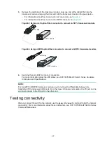
Page 49: ...4 16 Figure4 16 Connecting an SFP DAC cable 1 Pull latch 2 Connector 1 2 ...
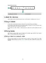
Page 92: ...A 12 FigureA 14 Example of a device label ...
Page 104: ...C 6 FigureC 5 Securing the chassis to the pallet base S12504G AF switch 1 1 2 2 1 ...


