background image

   DIGITAL 

I/O 

   87 

Application: Compare measurement


Applicable to 


Background 

Compare measurement checks and updates if  the 

measurement data stays between the upper (high) and 
lower (low) limit specified. 

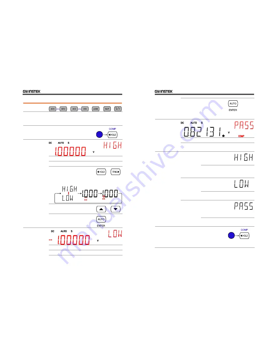
1. Activate 
Compare 
measurement 

Press the Shift key, then the HOLD 

(Comp) key. 


2. High limit 
setting 


 1st 

display 

Shows the high limit value 

 2nd 

display 

Indicates high limit setting 


1.


Use the Left/Right key to move 
the cursor (flashing point) 

between high/low setting, digits, 
and decimal point. 


2.


Change the parameter using the 
Up/Down key. 


3.


Press the ENTER key to 

confirm editing and move to the 
low limit setting. 


3. Low limit 
setting 


 1st 

display 

Shows the low limit value 

 2nd 

display 

Indicates low limit setting 


GDM-8200 Series User Manual 

88 


4.


Set the low limit in the same way 

as in the high limit. Press the 
ENTER key to confirm editing. 

The compare measurement 
starts right away. 


4. Compare 
measurement 
appears 


 COMP 

Indicates Compare mode 


2

nd

 display 

Shows the compare measurement result: 
Pass, High, or Low. 

5. Result 

High 

If  the 2

nd

 display shows 

High, the result is above 
the High limit. 


Digital I/O: FAIL Out (Pin 6) and 

HIGH Limit FAIL Out (Pin 7) are 
activated. 


Low 

If  the 2

nd

 display shows 

Low, the result is below 
the Low limit. 


Digital I/O: FAIL Out (Pin 6) and LOW 

Limit FAIL Out (Pin 8) are activated. 


Pass 

If  the 2

nd

 display shows 

Pass, the result is staying 

between the High and the 
Low limit. 


Digital I/O: PASS Out (Pin 5) is 

activated. 

Deactivate 
Compare 
measurement 

To cancel the Compare 
measurement, press the Shift key 

followed by the HOLD (Comp) key, 
or simply activate another 

measurement. 


Summary of Contents for GDM-8251

Page 1: ...ual may be photocopied reproduced or translated to another language without prior written consent of Good Will company The information in this manual was correct at the time of printing However Good W...

Page 2: ...easurement 43 Max Min Measurement 45 Relative Value Measurement 46 Hold Measurement 48 Compare Measurement 49 Math Measurement 52 Dual Display Measurement 56 SYSTEM DISPLAY CONFIGURATION 57 Refresh Ra...

Page 3: ...r obstruct the cooling fan vent opening Do not perform measurement at the source of low voltage installation or at building installations Note below Do not disassemble GDM 8200 series unless you are q...

Page 4: ...0 Series User Manual 8 Power cord for the United Kingdom When using GDM 8200 series in the United Kingdom make sure the power cord meets the following safety instructions NOTE This lead appliance must...

Page 5: ...Lineup 10 GDM 8200 Series Characteristics 11 Panel Overview Front Panel Overview 12 Measurement keys Upper row 13 Measurement keys Lower row 15 Rear Panel Overview 17 Setup Tilt Stand 19 Power Up 20 G...

Page 6: ...input 4W sense input USB host RS232 GPIB optional for remote control 9 pin digital I O 16 channel scanner x2 optional Optional Items GPIB module 16 channel scanner x 2 GDM 8200 Series User Manual 12 F...

Page 7: ...ltage page24 SHIFT ACV SCAN Starts the optional scan measurement page76 DCV Measures DC Voltage page24 GDM 8200 Series User Manual 14 SHIFT DCV STEP Starts the step measurement page76 using the option...

Page 8: ...trigger source page59 Left Right Selects the parameter in various occasions left or right REL Measures the Relative value page46 SHIFT REL RELative base Manually sets the reference value for the Relat...

Page 9: ...pts a USB host cable for remote control Type A male connector For remote control details see page91 CAL key port CAL KEY Reserved for internal uses as in firmware update and calibration GDM 8200 Serie...

Page 10: ...nual 20 Power Up Power up steps 1 Connect the power cord to the AC Voltage input Note Make sure the ground connector of the power cord is connected to a safety ground This will affect the measurement...

Page 11: ...ser Manual 22 Basic Measurement Overview Background Basic measurement refers to the eight types of measurements assigned to the upper row keys on the front panel Measurement type ACV AC Voltage DCV DC...

Page 12: ...anually GDM 8200 Series User Manual 24 AC DC AC DC Voltage Measurement Voltage type AC true RMS 0 750V DC 0 1000V AC DC 0 1000V AC RMS 2 DC 2 AC DC 1 Activate ACV DCV Press the ACV AC Voltage key or D...

Page 13: ...0V 199 999V 750V AC 10mV 750 0V 750 0V 1000V DC AC DC 10mV 1000 0V 1000 0V Note For more detailed parameters see the specification at page109 GDM 8200 Series User Manual 26 Voltage conversion table Th...

Page 14: ...Mixed frequencies 1 414 2 0 SCR output 100 10 1 414 3 0 White noise 3 0 4 0 AC Coupled pulse train 3 0 Spike 9 0 GDM 8200 Series User Manual 28 AC DC AC DC Current Measurement Current type AC true RM...

Page 15: ...pe 2 wire Uses the standard V COM ports Recommended for measuring resistances larger than 1k 4 wire Compensates the test lead effect using the 4W compensation ports in addition to the standard V COM p...

Page 16: ...k 120 000k 199 999k 1M 1 20000M 1 99999M 10M 12 0000M 19 9999M 100M 120 000M 199 999M Note For more detailed range see the specification at page112 GDM 8200 Series User Manual 32 Diode Test Background...

Page 17: ...ontinuity threshold Background Continuity threshold defines the maximum resistance allowed in the DUT when testing the continuity Threshold Range 0 1000 1 resolution 10 default 1 Activate threshold se...

Page 18: ...Right key Beeper type Pass beep when pass Fail beep when fail default Off beep off 3 Go back to the default display Press the Enter key to confirm Press the Exit key to go back to the default display...

Page 19: ...updates the reading V COM Range 0 300 C GDM 8200 Series User Manual 38 Select thermocouple type Background GDM 8200 series assumes that a certain type of thermocouple which reads voltage fluctuation...

Page 20: ...display 2 Edit reference temperature Use the Left Right key to move the cursor and use the Up Down key to change the value Default 23 00 Press the Enter key to confirm the value or the Exit key to can...

Page 21: ...n selecting the refresh rate Range S 5 digits M 4 digits F 3 digits Selection step 1 Press the Shift key followed by the AUTO RATE key The refresh rate switches to the next GDM 8200 Series User Manual...

Page 22: ...ance press the Up Down key The new impedance appears in the 2nd display The following is the impedance list 2 4 8 16 50 75 93 110 124 125 135 150 250 300 500 600 800 900 1000 1200 8000 GDM 8200 Series...

Page 23: ...elative measurement stores a value typically the data at the moment as the reference The following measurement is shown as the delta between the reference 1 Activate Relative measurement Press the REL...

Page 24: ...when the reading fluctuates more than the threshold setting as the percentage of the retained data 1 Activate Hold measurement Press the HOLD key 2 Hold measurement display appears HOLD Indicates Hold...

Page 25: ...setting digits and decimal point 2 Change the parameter using the Up Down key 3 Press the ENTER key to confirm editing and move to the low limit setting GDM 8200 Series User Manual 50 3 Low limit sett...

Page 26: ...measurement press the Shift key followed by the HOLD Comp key or simply activate another measurement GDM 8200 Series User Manual 52 Math Measurement Applicable to Background Math measurement runs thr...

Page 27: ...B 1st display Shows the calculated result 2nd display Indicates MX B MATH Indicates Math operation GDM 8200 Series User Manual 54 Measure 1 X 1 Activate 1 X Press the Shift key the 2 4W Math key the D...

Page 28: ...how another item thus viewing two different measurement results at once The following table shows the available options 1st Display 2nd Display ACV DCV ACI DCI Hz P ACV DCV ACV DCV ACI DCI ACI DCI 2W...

Page 29: ...es User Manual 58 Refresh Rate Setting Background Refresh rate defines how frequently GDM 8200 series captures and updates the measurement data Faster refresh yields better accuracy but lower resoluti...

Page 30: ...EOM Out VCC Out NC COM External Trigger In PASS Out Pin4 External Trigger Input pin GDM 8200 Series User Manual 60 1 Activate external trigger Press the Shift key followed by the TRIG key The EXT ind...

Page 31: ...s the averaging method The following diagrams show the filter difference as an example of averaging 4 samples per reading Moving default Moving filter takes in one new sample and discards the oldest s...

Page 32: ...al 64 Display Light Setting Background Display light setting adjusts the brightness of the display reading Use level 3 or more brighter when working indoor use level 2 or 1 darker when working outdoor...

Page 33: ...nge the data count using the Up Down key GDM 8200 Series User Manual 66 3 Press the Enter key to confirm editing and to go back to the previous display STO Indicates the measurement history is stored...

Page 34: ...lay ON Light level 3 5 digit Beep ON when Pass Scan Min 101 Max 116 Count 16 Timer 10ms RS 232C Baud 115200 GPIB Address 8 GDM 8200 Series User Manual 68 SCANNER OPTIONAL The scanner lets you effectiv...

Page 35: ...ight row Current ACI DCI measurement uses 2 extra channels All channels are fully isolated Hi and Lo Scan Step connection Refer to the below table for measurement and test line connection Item No of w...

Page 36: ...1 218 CH101 118 CH201 218 GDM 8200 Series User Manual 72 Connect wire Wire selection Make sure the wires have at least the same Voltage and Current capacity as the maximum ratings in the measurement C...

Page 37: ...Off and take off the power cord GDM 8200 Series User Manual 74 Open GDM 8200 series rear panel slot Take off the two screws on the slot corners to remove the optional slot cover Keep the screws for l...

Page 38: ...ts the duration between each scan loop Scan operation or between each scanned channel Step operation Count setting Sets the number of scan operation loop Trigger setting Internal Continuous GDM 8200 s...

Page 39: ...aximum channel setting appears GDM 8200 Series User Manual 78 6 Move the cursor to the channel using the Left Right key and change the value using the Up Down key Range 101 118 201 218 must be the sam...

Page 40: ...ppears GDM 8200 Series User Manual 80 Range 1 128 6 Move the cursor to the channel using the Left Right key and change the value using the Up Down key 7 When finished press the ENTER key The channel s...

Page 41: ...r timing Exit external trigger Press the Shift key followed by the TRIG key The EXT indicator disappears and the trigger goes back to the internal mode GDM 8200 Series User Manual 82 Run Scan Overview...

Page 42: ...un monitoring Panel operation 1 Press the Shift key the 2ND key MENU the Left key twice The Scan menu appears 2 Press the Down key followed by the Left key The Monitor Scan setting menu appears GDM 82...

Page 43: ...2 3 4 5 6 7 8 9 FAIL Out HIGH Limit FAIL Out LOW Limit FAIL Out EOM Out VCC Out NC COM External Trigger In PASS Out Pin1 VCC output 5V Serves as the power source for the external device logic Pin2 NC...

Page 44: ...limit setting GDM 8200 Series User Manual 88 4 Set the low limit in the same way as in the high limit Press the ENTER key to confirm editing The compare measurement starts right away 4 Compare measur...

Page 45: ...G key to start triggering manually The indicator turns On Reading indicator The reading indicator stays On before triggering After triggering the indicator flashes according to the external signal tri...

Page 46: ...enu appears 2 Press the Down key The USB selection display appears 3 Press the ENTER key to confirm USB selection GDM 8200 Series User Manual 92 4 Connect the USB cable to the rear panel terminal uppe...

Page 47: ...ent GPIB address 0 31 GDM 8200 Series User Manual 94 4 Move the cursor using the Left Right key Change the value using the Up Down key GPIB address 0 31 5 Press the ENTER key to confirm GPIB and addre...

Page 48: ...Last data byte with END message only for GPIB connection Message Separator semicolon Command separator GDM 8200 Series User Manual 96 Command Set Commands are non case sensitive Underline means a sing...

Page 49: ...e to J sens temp tco type Returns thermocouple type Parameter j type J k type K t type T sens temp rjun sim Set temperature simulation value Parameter NR2 Example sens temp rjun sim_23 GDM 8200 Series...

Page 50: ...ent Parameter NR2 calc math mbf Sets offset B in Math measurement Parameter NR2 Example calc math mbf_10 Math offset set to 10 calc math mbf Returns offset B in Math measurement Parameter NR2 calc mat...

Page 51: ...ls Clears event status register Output Queue Operation Event Status Questionable Event Status Standard Event Status ese Returns ESER Event Status Enable Register contents Example 130 means ESER 100000...

Page 52: ...nf2 curr ac_10e 3 AC Current 10mA range conf2 res Configure 2nd display to 2W Resistance Parameter NR2 min max Example conf2 res_10e2 2W Resistance 1k range conf2 fres Configure 2nd display to 4W Resi...

Page 53: ...result Shows the result of power on internal self test Firmware version Shows GDM 8200 series firmware version number View self test result 1 Press the Shift key followed by the 2ND Menu key The syste...

Page 54: ...wer cord and remove the fuse socket using a minus driver 2 Replace the fuse in the holder Rating T3 15A 250V GDM 8200 Series User Manual 108 Replace input current fuse Step 1 Press the Fuse holder 2 T...

Page 55: ...l Scale 8255 Accuracy 100 000mV 1 V 120 000mV 199 999mV 0 012 8 1 00000V 10 V 1 20000V 1 99999V 0 012 5 10 0000V 100 V 12 0000V 19 9999V 0 012 5 100 000V 1mV 120 000V 199 999V 0 012 5 S 1000 00V 10mV...

Page 56: ...10 00A 10mA 10 00A 10 00A 0 2 2 GDM 8200 Series User Manual 112 AC Current Note mA range protected with a 100mA fuse 10A range protected with a 12A 600V fuse 10A range specification is verified for 5k...

Page 57: ...120 000M 199 999M 3 0 8 100 00 120 00 199 99 0 05 5 1 0000k 1 2000k 1 9999k 0 05 3 10 000k 12 000k 19 999k 0 05 3 100 00k 120 00k 199 99k 0 05 3 1 0000M 1 2000M 1 9999M 0 05 3 10 000M 12 000M 19 999M...

Page 58: ...ients EN 61000 4 4 2004 Surge Immunity EN 61000 4 5 1995 A1 2001 Conducted Susceptibility EN 61000 4 6 1996 A1 2001 Power Frequency Magnetic Field EN 61000 4 8 1993 A1 2001 Voltage Dip Interruption EN...

Page 59: ...setting 30 specification 112 113 RS 232C configuration 92 S safety instruction fuse 6 power supply 6 symbol 5 scan operation front panel key 13 step operation 82 scanner command set 102 get out of sc...

Reviews: