Operating Manual
Initial Machine Set-up
12/19/02
19
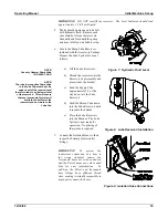
IMPORTANT: DO NOT overfill the reservoir. The Level Indicator should read
approximately 1/2 full with liquid.
5. The hydraulic pumps need to be full
with hydraulic fluid. Remove each
case drain hose from the reservoir.
Gradually add fluid until the pump
and hose is full and air bubbles stop.
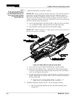
6. Locate the Pump Lube Reservoir
included with the Accessory Package.
Prepare the Lube System for use as
follows:
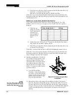
Figure 7. Hydraulic Fluid Level
NOTE:
Use only Gusmer Pump Lube
(P/N 0960-1-GAL)
NOTE:
The tube that supplies Pump Lube
to the Lube Cup must be at the
upper level of the reservoir and
the return tube is at the lower level
of the reservoir. This will ensure
that any Isocyanate Crystals will
settle to the bottom of the
reservoir and not return to the
Lube Cup
a) Fill the Lube Reservoir.
b) Thread the reservoir onto the
Reservoir Cap Assembly and
place it into the bracket.
c) Push the Supply Tube
approximately 1/3 of the
way down into the Lube
Reservoir.
d) Push the Return Tube down
into the Lube Reservoir until
it reaches the bottom.
e) Place the Lube Reservoir
into the Bracket. The Lube
System is now ready for
operation. No priming of
the system is required.
Figure 8. Lube Reservoir Installation
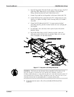
7. Connect the Isolation Hoses to their
respective Primary Heater outlet
fittings.
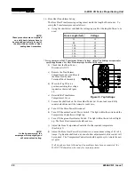
IMPORTANT: To prevent the
inadvertent connection of a hose to
the wrong chemical source, the
Isocyanate hoses are color-coded red
and the Polyol hoses are color-coded
blue for easy identification. In
addition, the Polyol and Isocyanate
hose fittings have different thread
sizes, making it virtually impossible to
improperly connect the hoses.
Figure 9. Isolation Hose Connections

