Operating Manual
Description
12/19/02
9
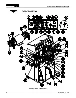
1. MAIN POWER DISCONNECT- Controls power to all circuits. Must be ON for
any function of the proportioning unit to operate. The disconnect can be locked in
the OFF position for OSHA required lockout/tagout during machine maintenance.
2. MAIN POWER LIGHT (WHITE)- Lights up when the Main Disconnect Switch is
in the ON position and the control power transformer is operational.
3. CONTROL POWER SWITCH- Turns the unit’s 120VAC control power circuit on
and off. In the ON position, the amber light within the switch lights up. Removal of
control power stops all machine operation including motion and heating.
4. EMERGENCY STOP SWITCH- Interrupts the units control power circuit to stop
all motion and heating. Switch mechanically locks in the stop position. Turn the
switch clockwise to reset it and restore normal operation.
5. HYDRAULIC MOTOR SWITCH- Controls power to motor circuit. In the ON
position, the green light within the switch lights up.
6. POLYOL COUNTER- Records the cycle count of the Polyol proportioning pump.
One cycle equals two strokes (one in each direction); used to determine ratio.
7. ISOCYANATE COUNTER- Records the cycle count of the Isocyanate
proportioning pump. One cycle equals two strokes (one in each direction); used to
determine ratio.
8. PUMP MODE SWITCH- Controls operation of the proportioning pump Hydraulic
Drive System
•
RUN- Should be in this position for the pump system to operate properly.
This position is used for all normal operation of the pump system, while
dispensing chemical. Hydraulic system will be energized when a special
dispensing gun is triggered.
•
RETRACT- The pump system is energized so that the Isocyanate pump
shaft is retracted into the pump cylinder. This shields the Isocyanate pump
shaft from air to limit crystallization during periods of machine inactivity.
The retract position should be used during any period of machine inactivity
•
SERVICE – With the recirculating ball valves open, the pump system is
energized and ratio can be determined with the counters or material can be
conditioned. With the recirculating ball valves closed, the system will build
pressure.
9. ISOCYANATE RECIRCULATING BALL VALVE – Ball valve on the Iso
material that either allows the system to recirculate chemical back to the chemical
drums during Service Pump Mode or prevents chemical from returning to the
chemical drums during Run Pump Mode.
10. POLYOL RECIRCULATING BALL VALVE – Ball valve on the Polyol material
that either allows the system to recirculate chemical back to the chemical drums
during Service Pump Mode or prevents chemical from returning to the chemical
drums during Run Pump Mode.


