background image

Operating Manual 

Maintenance 

12/19/02 

43 

P

UMP 

B

ASES


WARNING:


B

OTH PUMP BASES OPERATE UNDER HIGH PRESSURE

.  T

O AVOID SERIOUS 

BODILY INJURY

USE EXTREME CAUTION TO ENSURE ALL PRESSURE FROM BOTH THE SUPPLY 

AND DELIVERY SIDE OF THE PUMP BASE HAVE BEEN BLED TO ZERO BEFORE SERVICING THE 

PUMP BASE ASSEMBLY


Disassemble and clean both Pump Bases annually as follows: 
(Refer to the Pump Base Assembly section of the Parts I.D. for reference.) 


1.  De-pressurize the system. 


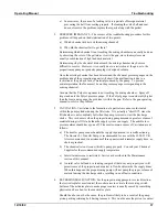
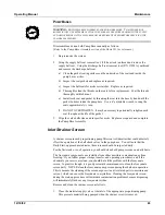
2.  Using the supply ball seat removal tool, (5/8 hex stock) unthread and remove the 

supply ball seat.  Using the discharge ball seat removal tool (P/N 17928A), unthread 
and remove the discharge ball seat. 


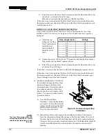
a)  Clean the gasket seating surfaces on the underside of the seats and inside the 

pump base cavities. 

b)  Inspect the seat gaskets and replace as required. 

c)  Inspect the ball seats for nicks or scratches.  Replace as required.  

d)  Thoroughly clean the threads on the seats before replacement.  Coat the threads 

thoroughly with lubricant. 

e)  Install each seat and gasket by threading the seat into the base by hand until the 

gasket bottoms inside the pump base.  Use a 6” adjustable wrench to snug the 
seats approximately ¼ turn. 

f)  DO NOT OVERTIGHTEN.  It may be necessary to periodically retighten each 

seat throughout the life of the gasket. 


3.  Wipe the valve balls clean and inspect for nicks.  Replace as required and complete 

the Pump Base Assembly. 

Inlet Strainer Screen 


A strainer screen in each proportioning pump filters out solid matter that could adversely 
effect the operation of the ball check valves in the pump base.  You will note that the 
Daily Start-up procedure indicates these screens should be inspected daily. 


For the first week or so of operation, you should clean both pump screens on a daily basis. 


The Isocyanate component can crystallize from either moisture contamination or from 
freezing.  If you follow proper storage, transfer, and operating procedures, and if the 
chemicals you receive are clean, you should have little problem with the Isocyanate 
screen.  In practice though, it is good preventative maintenance to clean the Isocyanate 
screen daily.  NEVER clean the Isocyanate pump screen during the shutdown operation.  
This is because the cleaning of the screen exposes it and its related parts to moisture and 
solvent, which can cause the Isocyanate to crystallize.  Cleaning the Isocyanate screen 
during the start-up procedure will minimize contamination problems because dispensing 
will immediately flush out any Isocyanate residue. 


Remove and clean the strainer screen as follows: 


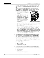
1.  Close the material supply valve at the inlet of the appropriate proportioning pump.  

This prevents material being pumped when the strainer screw is removed. 

Summary of Contents for H-20/35

Page 1: ... Subsidiary of Gusmer Machinery Group Inc One Gusmer Drive Lakewood New Jersey USA 08701 8055 Toll Free 1 800 367 4767 USA Canada Phone 732 370 9000 Fax 732 905 8968 Copyright 2002 GUSMER CORPORATION http www gusmer com NOTICE This manual contains important information about your GUSMER equipment Read and retain for future reference ...

Page 2: ... and telephone number of your local distributor NOTICE All statements information and data given herein are believed to be accurate and reliable but are presented without guarantee warranty or responsibility of any kind expressed or implied Statements or suggestions concerning possible use of GUSMER equipment are made without representation or warranty that any such use is free of patent infringem...

Page 3: ...ROCEDURES 27 DAILY SHUT DOWN PROCEDURES 28 TROUBLESHOOTING 29 GENERAL INFORMATION 29 HOSE HEAT SYSTEM 30 Solutions 30 PRIMARY HEATERS 33 Solutions 34 PROPORTIONING SYSTEM 35 Solutions 36 HYDRAULIC DRIVE SYSTEM 39 Solutions 40 MAINTENANCE 41 PRIMARY HEATERS 41 Heating Element Replacement 41 Thermocouple Replacement 42 PROPORTIONING SYSTEM 42 Proportioning Pumps 42 Pump Bases 43 INLET STRAINER SCREE...

Page 4: ...ON 19 FIGURE 9 ISOLATION HOSE CONNECTIONS 19 FIGURE 10 HEATED HOSE ASSEMBLY CONNECTIONS 20 FIGURE 11 TEMPERATURE SENSING UNIT TSU 21 FIGURE 12 TEMPERATURE CONTROLLER 23 FIGURE 13 TAP SETTINGS 24 FIGURE 14 HOSE HEAT POWER SET 30 FIGURE 15 HOSE HEAT CIRCUIT BREAKER 31 FIGURE 16 TERMINAL JUMPER STRIP INSTALLATION 32 FIGURE 17 PRIMARY HEATER 33 FIGURE 18 PRIMARY HEATER CIRCUIT BREAKERS 34 FIGURE 19 PR...

Page 5: ... will be done in accordance with the terms stated on the written estimate The warranty provisions applied to product that are not manufactured by Gusmer will be solely in accordance with the warranty provided by the original manufacturer of the product GUSMER MAKES NO WARRANTY WHATSOEVER AS TO THE MERCHANTABILITY OF OR SUITABILITY FOR ITS PRODUCT TO PERFORM ANY PARTICULAR PURPOSE CREDIT FOR OR REP...

Page 6: ...t must therefore make their own determination as to the suitability of the information contained in this manual to their specific operation and requirements There should be no assumption made that the safety measures and instructions contained herein are all inclusive and that other safety measures may not be required for specific use or application The following safety guidelines are generally ap...

Page 7: ...RUPTING SUPPLY VOLTAGE AT THE SOURCE THE ELECTRICAL SERVICE MUST BE INSTALLED AND MAINTAINED BY A QUALIFIED ELECTRICIAN High Pressure WARNING THIS EQUIPMENT HAS OR IS USED WITH EQUIPMENT THAT HAS HYDRAULIC AND CHEMICAL COMPONENTS CAPABLE OF PRODUCING UP TO 3500 PSI TO AVOID SERIOUS BODILY INJURY FROM INJECTION OF FLUID NEVER OPEN OR SERVICE ANY CONNECTIONS OR COMPONENTS WITHOUT BLEEDING ALL PRESSU...

Page 8: ...H 20 35 VR Series Proportioning Unit 8 42942 VR 1 Issue 1 DESCRIPTION Figure 1 Major Components ...

Page 9: ...two strokes one in each direction used to determine ratio 8 PUMP MODE SWITCH Controls operation of the proportioning pump Hydraulic Drive System RUN Should be in this position for the pump system to operate properly This position is used for all normal operation of the pump system while dispensing chemical Hydraulic system will be energized when a special dispensing gun is triggered RETRACT The pu...

Page 10: ...ic pressure available to the Hydraulic Drive System This adjustment must be set high enough so the pump will not reduce flow rate for the Polyol pump 18 HOSE HEATER SWITCH Energizes the Hose Heat System circuit In the ON position the green light within the switch lights up 19 HOSE HEAT TEMPERATURE CONTROLLER Digital display of controller will be energized when Control Power Switch is activated Con...

Page 11: ...Isocyanate proportioning pump exceeds the safe pressure limitation 30 POLYOL LOW PRESSURE SAFETY SWITCH Turns off the Hydraulic Drive System when the Polyol proportioning pump falls below 40 psi Not Shown 31 ISOCYANATE LOW PRESSURE SAFETY SWITCH Turns off the Hydraulic Drive System when the Isocyanate proportioning pump falls below 40 psi 32 POLYOL PRESSURE GAUGE Indicates the pressure in the Poly...

Page 12: ...low in the Hose Heat System Heating Element as required by the Temperature Controller 49 HOSE HEAT SSR JUMPER The jumper is used to bypass the hose heat system SSR in the event that the SSR fails This allows continued to operation of the machine by running the Hose Heat System manually See step 10 on page 32 Figure 2 Transformer Compartment Electrical Components 50 HOSE HEAT SYSTEM CIRCUIT BREAKER...

Page 13: ...Operating Manual Description 12 19 02 13 ...

Page 14: ...H 20 35 VR Series Proportioning Unit 14 42942 VR 1 Issue 1 Figure 3 Electrical Console Components ...

Page 15: ...y Heater which controls the contactor 63 HOSE HEAT CONTACTOR Supplies line voltage to Hose Heat System The Hose Heater Switch controls the contactor 64 MOTOR CIRCUIT PROTECTOR Provides thermal overload and over current protection for the hydraulic motor circuit 65 ISOCYANATE HEATER CIRCUIT BREAKER Provides over current protection for the Iso Primary Heater circuit 66 POLYOL PRIMARY HEATER CIRCUIT ...

Page 16: ...29 Liters Recommended operating temperature 120 F 48 C Maximum operating temperature 160 F 71 C WEIGHT Empty 685pounds 311 kilograms Serviced 1025 pounds 465 kilograms DIMENSIONS Height 47 inches 119 centimeters Width 40 inches 102 centimeters Depth 22 inches 56 centimeters DISPENSING PRESSURE H 20 VR 1900 psi maximum 131 Bars H 25 VR 2400 psi maximum 165 bars SUPPLY PRESSURE 400 psi maximum 27 Ba...

Page 17: ...Operating Manual Initial Machine Set up 12 19 02 17 INITIAL MACHINE SET UP Figure 4 Typical Installation Consult Gusmer Sales for the correct hose sizes for your application ...

Page 18: ...t the source 1 Connect the main power cord to the electrical console as follows See Figure 5 and Figure 6 Figure 5 Main Power Connection a Feed the power cord through the strain relief in the bottom of the console Connect the power leads to L1 L2 and L3 For 380V 3 Phase units connect the neutral wire to the blue neutral terminal block on the circuit breaker rail b Connect the ground wire to the Gr...

Page 19: ... the bottom of the reservoir and not return to the Lube Cup a Fill the Lube Reservoir b Thread the reservoir onto the Reservoir Cap Assembly and place it into the bracket c Push the Supply Tube approximately 1 3 of the way down into the Lube Reservoir d Push the Return Tube down into the Lube Reservoir until it reaches the bottom e Place the Lube Reservoir into the Bracket The Lube System is now r...

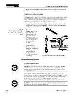
Page 20: ...e care not to cross thread or over tighten the fittings ensuring a leak proof chemical connection b Tape the Isolator securely in place between the hydraulic fittings IMPORTANT While the Isolator is no longer used to prevent an electrical short its purpose is now to protect the fittings Figure 10 Heated Hose Assembly Connections c Connect the Air Hoses and tighten the fittings with open end wrench...

Page 21: ...tor boot over each plug and tape together f Cut the Isolator in two and secure the two pieces in place between the hydraulic fittings g Plug the Hose Heat Power Lock Connectors together Secure the connection in place with the Cable Tie provided failure to do so could cause a disruption in the Hose Heat System Figure 11 Temperature Sensing Unit TSU WARNING THE TEMPERATURE SENSOR EXTENDS APPROXIMATE...

Page 22: ...y Valves It is a good practice at this point to check for chemical leaks NOTE If the inlet chemical pressure is below 40 psi the audible alarm will sound when the Control Power Switch is turned ON c Turn the Hydraulic Pump Flow Adjustment clockwise for both pumps until approximately of the adjustment is showing d Turn ON the red Main Disconnect The white Main Power Light will light up e Turn ON th...

Page 23: ...HEATERS COMPLETELY FILLED WITH CHEMICAL ADDITIONALLY DO NOT CHANGE ANY OF THE PREPROGRAMMED PARAMETERS a Check that the red Main Disconnect is ON The white pilot light and the Temperature Controllers should be lit b Check that the amber Control Power Switch is ON The light within the switch should be lit NOTE The Temperature Controller normally displays the Set Point The red LED number1 on the Tem...

Page 24: ... position matching the voltage required as shown in Figure 16 e Reinstall the Transformer Compartment Cover Figure 13 Tap Settings f Loosen the shaft lock on the Hose Heat Power Set Control and turn it fully counter clockwise until the Ammeter reads zero g Turn ON the Main Power Disconnect h Turn ON the amber Control Power Switch The light within the switch and the Temperature Controllers will lig...

Page 25: ...at there is pressure present 8 Both the Iso and Polyol Hydraulic Pump Pressure Gauges should be set to 1200 psi Adjustment clockwise to increase pressure and counter clockwise to decrease pressure NOTE Both chemical pumps will move back and forth Chemical is now being returned back to the chemical drums 9 Turn the Pump Mode Switch to SERVICE NOTE Prior to leaving the factory the unit was set for a...

Page 26: ...3 29 40 12 48 5 68 8 32 3 76 45 14 04 6 39 9 36 4 23 50 15 60 7 1 10 40 4 7 55 17 16 7 81 11 44 5 17 60 18 72 8 52 12 48 5 64 13 Repeat step 9 14 Turn the Pump Mode Switch to RUN 15 Tighten lock nut on Hydraulic Pump Flow Control Adjustments and replace caps NOTE Both the locking nut and caps contain o ring seals 16 Close the Recirculating Ball Valves If all steps have been followed and no problem...

Page 27: ... point If the set point needs to be changed see Step 15 in Initial Machine Set up 10 Adjust the Hose Heat Power Set clockwise to a maximum of 45 to 50 Amps Tighten the shaft lock nut IMPORTANT To prevent excessive pressure buildup in the heated hoses always bring the hoses up to temperature before turning on the Hydraulic system The red LED number1 on the Hose Heat Controller when illuminated indi...

Page 28: ...nnect air to the spray gun Consult the spray gun operating manual and test spray as per the directions Daily Shut down Procedures 1 Open the Recirculating Ball Valves on the front of the machine 2 Turn the Pump Switch to RETRACT NOTE Chemical Pumps should move to the RETRACT position and stop 3 Turn OFF the green Hydraulic Motor Switch The light within the switch will go out 4 Turn OFF the green I...

Page 29: ...Technician Obtain information on these schools from our sales office GUSMER maintains a competent staff of Technical Representatives and authorized Distributors who can resolve almost any problem you may encounter with GUSMER equipment Feel free to call on these people for assistance when you need it WARNING THE TROUBLESHOOTING SECTION OF THIS MANUAL ASSUMES THAT THE INDIVIDUAL PERFORMING THE WORK...

Page 30: ...reach temperature 1 2 8 Hose does not heat red LED on the Hose Heat Controller is ON 2 3 4 6 9 10 Hose Heat Controller does not cycle automatically red light on the controller is ON 4 5 6 10 Hose Heat Circuit Breaker trips 2 3 Hose temperature not maintained during flow 2 7 8 Hose or hoses adjacent to the unit are warm hoses downstream are cold 9 SOLUTIONS 1 HOSE LENGTH The design of the H 20 35 V...

Page 31: ...tly into the TSU Extension Harness Change the TSU if control is not restored If control is restored systematically check each section of the TSU Wire Harness out to the gun 7 PRIMARY HEAT AND HOSE HEAT SETTINGS The purpose of the Hose Heat System is not to add heat but rather to maintain the temperature developed by the Primary Heater If it appears that the Hose Heat System is not maintaining temp...

Page 32: ... fault is within the last unplugged segment of hose If hose heat is not restored adjust the Hose Heat Power Set counterclockwise until the Ammeter reads zero then turn OFF power to the Hose Heat System and repeat Steps c through e until the fault is located 10 MANUAL HOSE HEAT CONTROL It is possible to bypass the Hose Heat System and operate the Hose Heat System manually This feature allows for co...

Page 33: ...ITHER COVER BOX WITHOUT FIRST SWITCHING OFF THE MAIN POWER DISCONNECT WARNING HIGH TEMPERATURE EXISTS INSIDE THE PRIMARY HEATER COVERS NEVER OPERATE THE PROPORTIONING UNIT WITH EITHER HEATER COVER BOX REMOVED COOL THE FLUID IN THE HEATER BY PUMPING UNHEATED FLUID THROUGH THE HEATER WITH THE HEATER OFF TO AVOID BODILY INJURY FROM HOT FLUID AND HOT METAL Figure 17 Primary Heater Try the recommended ...

Page 34: ...e another To determine if a controller is operating correctly turn OFF the red Main Disconnect and replace the suspect controller with one known to be good 5 THERMOCOUPLE The temperature controller s design includes a fail safe feature that prevents the heating system from operating in the event that there is no signal from the thermocouple In this case replace the thermocouple Refer to the Mainte...

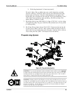
Page 35: ... the H 20 35 VR maximizes the heat transfer from the power available However under certain conditions the heater will not be able to reach the required temperature and will require a reduction in flow or the use of an auxiliary hose heat system Call Gusmer Sales for information Proportioning System Figure 19 Proportioning System WARNING TO AVOID SEVERE BODILY INJURY OR DEATH FROM ELECTRIC SHOCK DO...

Page 36: ...MOVING TO THE LEFT IF CHEMICAL PUMP IS MOVING TO THE RIGHT Polyol Discharge Ball Check Valve or components fouling Polyol Pump Inlet Ball Check Valve or components fouling Iso Inlet Ball Check Valve or components fouling Iso Pump Discharge Ball Check Valve or components fouling To service perform the following procedure a Shut off all electrical switches breakers and the main power supply b Close ...

Page 37: ...m 3 CAVITATION Cavitation is the formation of a partial vacuum or void created within the pump cylinder during the fill stroke It is actually a short fill since the fill chamber is not completely full when the pump reverses to start the discharge stroke This void occurs when the proportioning pump demands a greater volume of material during its fill stroke than the supply system can supply The aud...

Page 38: ...the SERVICE position The pumps should cycle back and forth freely if the activator plate contacts the reversing switch and does not change direction it is probable that an electrical problem exists in the reversing switch directional valve coil or Pump Switch Should the spool hang up or be hard to push it is likely that there is a mechanical problem within the directional valve which will necessit...

Page 39: ...cally start and stop the pump circuit of the system This gun contains a switch that senses a magnet in the gun piston When the piston of the gun retracts the magnetic switch closes and completes an electrical circuit enabling the unit to start dispensing The most likely causes of non operating pumps are a Incorrect gun being used b Magnetic switch on the dispensing gun out of adjustment c Magnetic...

Page 40: ...to NORMAL the major cause of zero or low pressure is a pump that is not primed or loses its prime To ensure a positive prime proceed as follows a Check for correct Electric Motor Rotation See step 13 in the Initial Machine Setup section of this manual b Make sure hydraulic reservoir is filled to the proper level c Make sure pump case is full with hydraulic fluid d Make sure inlet fitting is proper...

Page 41: ...W HEATER TO COOL TO AVOID BODILY INJURY FROM HOT FLUID OR HOT METAL The sheaths on the H 20 35 VR Heating Rods are made from a special alloy designed to be resistant to corrosion and erosion However the maximum service life of the rod will eventually be reached and if the sheath should fail fluid under pressure will leak into the heating element This may result in leakage through the potting at th...

Page 42: ...ating element Make sure that the Heat Exchanger Spring does not obstruct the placement of the element 3 Firmly hold the Thermocouple in place against the element and using an open end wrench tighten the Compression Nut Note the correct ferrule positioning Figure 22 Thermocouple Components Proportioning System PROPORTIONING PUMPS WARNING THE CHEMICAL COMPONENTS ARE PRESSURIZED UP TO 3500PSI BEFORE ...

Page 43: ...roughout the life of the gasket 3 Wipe the valve balls clean and inspect for nicks Replace as required and complete the Pump Base Assembly Inlet Strainer Screen A strainer screen in each proportioning pump filters out solid matter that could adversely effect the operation of the ball check valves in the pump base You will note that the Daily Start up procedure indicates these screens should be ins...

Page 44: ... do its job check its condition on a daily basis Change the pump lube before it becomes a gel or when its color becomes the same as the Isocyanate The gel formation is due to moisture absorption by the pump lube The time interval between changes due to gel formation depends entirely upon the environment in which the equipment is operating The enclosed pump lube system in the H 20 35 VR minimizes e...

Page 45: ... cleanliness as follows 1 Thoroughly clean the tank top the access cover plate and the components in the area of the cover plate This will ensure that no foreign matter will enter the hydraulic reservoir when removing the cover plate 2 Remove the six 6 cover plate mounting screws Separate the hydraulic suction pipe from the fitting connecting the pipe to the hydraulic pump 3 Remove the cover and p...

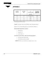
Page 46: ...n 220 Volts 3 Phase Formula This formula is useful for calculating the output of the proportioning unit Q lbs min C cycles min ISO pump C cycles min POLYOL PUMP x 31 Recommended Hydraulic fluid or equivalent 1 Mobil DTE 24 2 Mobil DTE 25 3 Cooks Albavis 10 The H 20 35 VR Series interfaces with all of the following equipment GAP Spray Gun 35100 R 02 SW GX 8 400 Spray Gun 32140 CSTM IMPORTANT Refer ...

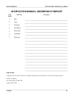
Page 47: ...umber Field Title Description 1 Date 2 Name 3 IM Number 4 Issue Number 5 Date of Issue 6 Page Number 7 Discrepancy Instructions Complete the above fields of the form by following the instructions listed on the reverse side of this sheet and mail to Gusmer Corporation One Gusmer Drive PO Box 2055 Lakewood NJ 08701 ...

Page 48: ...age 4 Issue Number Enter the Issue number of the Instruction Manual from the title page If there is no issue number enter NONE 5 Date of Issue Enter the date of Issue of the Instruction Manual from the title page If there is no issue date enter NONE 6 Page Number Enter the page number containing the discrepancy 7 Discrepancy Provide a brief description of discrepancy NOTE You may send a marked cop...

Reviews: