H-20/35 VR Series Proportioning Unit
34
42942-VR-1, Issue 1
S
OLUTIONS
1. THERMAL LIMIT SAFETY SWITCH- A completely independent, over-
temperature safety circuit has been provided and consists of four (4) thermal limit
safety switches attached to the heating tube(s). When the surface temperature of the
tube(s) exceeds 230° F, the thermal limit safety switch will automatically interrupt
the Primary Heater Control Contactor circuit. The temperature of the Primary Heater
must cool down to within limits before you can reset the Primary Heater ON/OFF
Switch. DO NOT attempt to reset the circuit breaker more than once. You must
determine the cause of the problem and correct it.
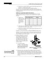
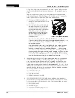
2. PRIMARY HEATER CIRCUIT
BREAKER- Turn OFF the red
Main Disconnect. Open The
Console Cover. Reset the
Primary Heater Circuit Breaker
if necessary.
3. PRIMARY HEATER SOLID
STATE RELAY (SSR)-
Checking for normal SSR
operation is not possible without
electric power. Therefore, if all
other testing fails to determine
the source of problem, assume
the SSR is inoperative and
replace it.
Figure 18. Primary Heater Circuit Breakers
4. PRIMARY HEATER CONTROL UNIT- The three Temperature Controllers on the
H-20/35 VR are directly interchangeable with one another. To determine if a
controller is operating correctly, turn OFF the red Main Disconnect and replace the
suspect controller with one known to be good.
5. THERMOCOUPLE- The temperature controller’s design includes a fail-safe feature
that prevents the heating system from operating in the event that there is no signal
from the thermocouple. In this case, replace the thermocouple. Refer to the
Maintenance section of this manual for the proper procedures.
6. HEATING ELEMENTS- The heater contains four 1500-Watt (32-ohm) heating
elements wired in parallel. To check operation of the elements proceed as follows:
a) With Main Power OFF, read the resistance across terminal #2 on the Polyol SSR
and terminal T2 on the Polyol Heater Contactor.
b) With Main Power OFF, read the resistance across terminal #2 on the Isocyanate
SSR and terminal T2 on the Isocyanate Heater Contactor.
The resistance should be 8 ohms. A higher resistance indicates that one or more
heating elements are inoperative. If this is the case, disconnect the heating elements
and measure the resistance of each element. Each heating element should measure 32
ohms. If not replace the damaged element or elements.
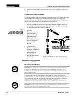
The positioning of the thermocouple in the outlet heat exchanger is critical to the
proper operation of the primary heater. Therefore, two conditions must be satisfied:
1) The thermocouple must make positive contact with the heating element.

