H-20/35 VR Series Proportioning Unit
24
42942-VR-1, Issue 1
16. Hose Heat Transformer Set-up:
The Hose Heat Transformer tap settings must match the length of hose in use. To
set-up the Transformer proceed as follows:
a) Using the chart below establish the voltage required for the length of hose to be
used.
Hose Length (feet)
Voltage
35 15
60 15
110 30
160 45
210 60
260 75
NOTE:
These procedures are not required
on a daily basis but may have to
be executed periodically as part of
the daily start-up routine or when
adding Hose Assemblies.
310 90
* Tests performed at 240V Transformer Primary Voltage. Adjust Tap Settings as required for
specific applications. Set Hose Heat Amperage between 40-50 Amps.
b) Check that the Main Power
Disconnect is OFF.
c) Remove the Transformer
Compartment Cover and locate
the Hose Heat System
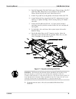
Terminal Block Assembly.
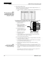
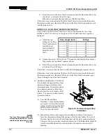
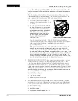
d) Move the Tap Wire to a
position matching the voltage
required as shown in Figure
16.
e) Reinstall the Transformer
Compartment Cover.
Figure 13. Tap Settings
f) Loosen the shaft lock on the Hose Heat Power Set Control and turn it fully
counter-clockwise until the Ammeter reads zero.
g) Turn ON the Main Power Disconnect.
h) Turn ON the amber Control Power Switch. The light within the switch and the
Temperature Controllers will light up.
i)
Turn ON the green Hose Heater Switch. The light within the switch will light
up. The Hose Heat Ammeter should read zero.
j)
Adjust the Hose Temperature Controller for the required temperature.
(See Step 15)
NOTE:
As the hoses warm up, the
amperage will drop slightly and
will not need readjusting.
k) Adjust the Hose Heat Power Set (clockwise) to a maximum setting of 45 to 50
Amps. Tighten the shaft lock nut, as no further adjustments to this control will
be required. The Temperature Controller should begin to cycle toward the new
set point.
If all steps have been followed and no problems have been encountered, the
H-20/35 VR should now be ready for ratio adjustment.

