


DA98D User Manual
29
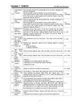
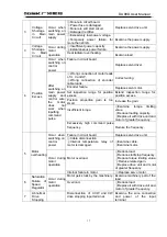
8
Low Pass
Filter for
Speed
Inspection
Set features of low pass filter for speed inspection.
The lower the value is, the smaller will be the cut-off frequency will
be and the less the motor noise. If the load inertia is very great, the
set value can be properly reduced. If the value is too low, the
response will become slow and may cause vibration.
The higher the value, the greater the cut-off frequency will be and
the faster the response. If relatively fast response is needed, the
set value can be properly increased.
1%~500%
9
Position
Proportion
Gain
Set proportion gain of the position regulator.
The higher the value is, the greater the gain will be and the less the
position lagging amount will be under the condition of command
pulse with the same frequency. But if the value is too high, it may
cause vibration or over-adjustment.
The parameter is determined by specific models of the servo drive
unit and concrete loads.
1~1000 /S
10
Position
Feed-forward
Gain
Set feed-forward gain of the position loop.
When the value is set at 100%, it means that the position lagging
value will be always 0 under command pulse with any frequency.
If the position feed-forward gain is increased, the high-speed
response feature of the control system will be enhanced, but the
position loop of the system will be instable and easy to cause
vibration.
If not specially requiring very fast response, the feed-forward gain
of the position loop is generally set as 0.
0%~100
%
11
Low Pass
Filter Cut-off
Frequency
for Position
Feed-forward
Set low pass filter cut-off frequency of the position feed-forward.
The function of this filter is to enhance stability of the composite
position control.
1 Hz ~
1200Hz
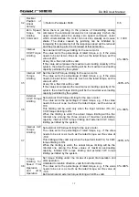
12
Position
Command
Pulse
Frequency
Division
Numerator
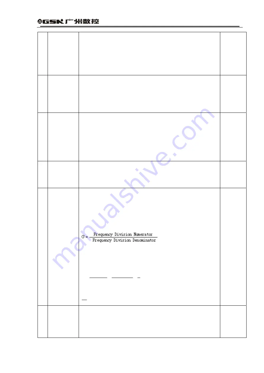
Set frequency division of the command pulse (electronic gear).
Under position control mode, it can be conveniently matched with
various pulse sources by setting PA12 and PA13 parameters, thus
reaching the ideal control resolving power (i.e. angle/pulse)
required by the user.
4
×
×
=
×
C
N
G
P
P: Pulse number of the input command;
G: Electronic gear ratio;
N: Motor rotation rounds;
C: Coil round number of the photoelectric encoder. In this system C
=
2500.
〖
Example
〗
if the input command pulse is 6000, the servo motor
rotates one round:
3
5
6000
4
2500
1
4
=
×
×
=
×
×
=
P
C
N
G
then the parameter PA12 is set as 5 and PA13 as 3.
⑤
Recommended range of electronic gear ratio:
50
50
1
≤
≤
G
1~32767
13
Position
Command
Pulse
Frequency
Division
Denominator
①
Refer to parameter PA12.
1~32767
Summary of Contents for DA98D
Page 1: ...DA98D Digital AC Servo Drive Unit User Manual V5 00 ...
Page 15: ...DA98D User Manual 4 Fig 1 1 Appearance of Servo Drive unit 2 Servo motor appearance ...
Page 16: ...DA98D User Manual 5 Fig 1 2 Servo Motor Appearance ...
Page 23: ...DA98D User Manual 12 Fig 3 1 Standard Wiring for Position Control Mode AM26LS32 Receiver ...
Page 24: ...DA98D User Manual 13 Fig 3 2 Standard Wiring for Speed Control Mode AM26LS32 Receiver ...
Page 71: ...DA98D User Manual 60 Installation Dimension Drawing for BS 120 Model ...
Page 72: ...DA98D User Manual 61 Installment Dimension Drawing for BS 200 Model ...
Page 73: ...DA98D User Manual 62 Installment Dimension Drawing for BS 300 Model ...
Page 74: ...DA98D User Manual 63 Installment Dimension Drawing for BD 80 Model ...
Page 75: ...DA98D User Manual 64 Installment Dimension Drawing for BD 120 Model ...


